Instrument Alignment in SA: Exploring the Possibilities
 Obtaining the most accurate measurement information as efficiently as possible is critical to metrologists. The accuracy of measurements depends on the quality and calibration of the instrument that takes those measurements, and the ability to compare those measurements to either an ideal model or expected values taken from another source. While instrument accuracy and calibration are the responsibility of the instrument manufacturer, measurement software allows you to compare the raw values provided by the instrument to a design (nominal) part or measurements taken from a second instrument. To do this, you need to locate or align your instrument in 3D space to the part being measured, or the other instruments or measurements to which you are comparing.
 Instrument Alignment in SA: Exploring the Possibilities
Obtaining the most accurate measurement information as efficiently as possible is critical to metrologists. The accuracy of measurements depends on the quality and calibration of the 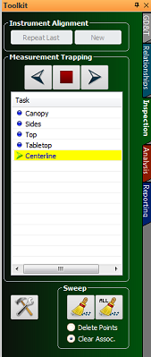 instrument that takes those measurements, and the ability to compare those measurements to either an ideal model or expected values taken from another source. While instrument accuracy and calibration are the responsibility of the instrument manufacturer, measurement software allows you to compare the raw values provided by the instrument to a design (nominal) part or measurements taken from a second instrument. To do this, you need to locate or align your instrument in 3D space to the part being measured, or the other instruments or measurements to which you are comparing.
SpatialAnalyzer® (SA) offers comprehensive alignment capabilities that allow you to align measurements taken from a single instrument station, as well as align networks of instruments together without error propagation. In this article, we’ll review SA’s numerous single instrument alignment options:
Instrument Alignment in SA:
To understand alignment in SA, remember the following:
- The connection between the points measured by an instrument and the instrument that measured them is always maintained. This is the key to SA’s traceability and ease of alignment.
- Therefore, when you move an instrument station, the points that were measured by that instrument move along with the instrument in 3D space.
- There are multiple ways in SA to align an instrument to a CAD model or a nominal part. These options can be found either through the menus by going to Instrument> Location (Transform to Part) or by right-clicking on the instrument in the graphic view and selecting “Locate.”
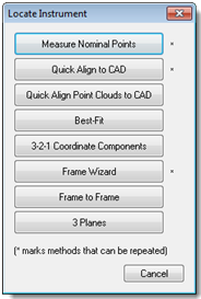 SA’s seven alignment options (see menu to the right) can be categorized into four primary types of transformations:
- Best Fit
- Frame to Frame
- Quick Align To CAD
- USMN & Bundling
Best Fit Alignments
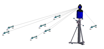
 Locating an instrument using a Best-Fit alignment is one of the most common location methods. It is often used during instrument location to nominal control points, instrument relocation, and relocation due to drift. You can specify the instrument to locate, the nominal point group, and measured point group, and SA will fit the groups together with the lowest possible RMS error.
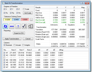
Performing a Best-Fit also provides complete control of the degrees of freedom constrained in the fit and allows you to include and exclude individual measurements prior to accepting the final transformation. This can be performed after measurements have been taken or interactively through an auto-measure mode initiated by selecting “Measure Nominal Points.” SA will then walk you through the measurement process and perform the fit automatically after the points have been measured.
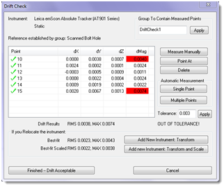
Drift Checks (Instrument>Drift Check) are also Best-Fit operations with the added benefit of automatically showing you what your deltas would look like if a refit were performed, keeping both scale constant and allowing scale to vary prior to accepting the transformation. If a Best-Fit with fixed scale significantly improves the results, it would indicate that the instrument has moved relative to your monuments. If a Best-Fit with scaling is required, then your reference system has scaled, and therefore the part has likely scaled as well. The Drift Check dialog provides two options: Add New Instrument: Transform and Add New Instrument: Transform and Scale which will conveniently add another instrument, activate its interface, and place you into a completed Measure Nominals dialog. This allows you to apply a Best-Fit or Best-Fit with varying scale without measuring any additional points.
Frame to Frame Alignments
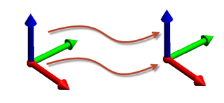
A coordinate frame defines an exact six-dimensional position in space, including both position and rotational information. A second category of alignment in SA allows you to define a coordinate frame based on measurements and then fit that frame to the active frame in the file, already at a known location. This can be accomplished in several ways. The simplest is a Frame to Frame alignment. This gives you a direct way to move an instrument from its starting position to a new position in a single step.
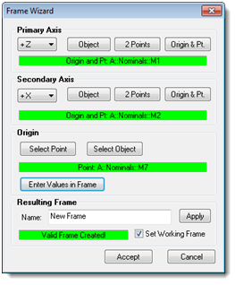
If you have measurements, but lack a frame constructed in the job file, Frame Wizard provides a flexible way to select points or objects to define the origin and axis directions of a new frame. Once that frame is built and you accept it, the transformation from the current frame location to the active frame is performed instantly.
An alternative to Frame Wizard is to use a 3 Planes alignment. In this case, you are building three planes whose directions define the axes of the coordinate system without needing an origin point. The planes defining the axis directions are then utilized to establish the origin point, and the frame defined by these measured planes is then used in the transformation process.
Similar to a GD&T alignment, it is often useful to define a primary, secondary, and tertiary alignment structure. A 3-2-1 Coordinate Components fit consists of a locator point for the origin, line/vector for one axis, and plane for the second axis. The Plane, Line, Point Transformation dialog allows control over the axis for the plane and line/vector. The user may also specify an alternate coordinate for the locator point. Once the transformation is accepted, the instrument will be transformed with respect to the active frame.
Quick Align to CAD
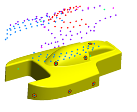
Quick Align is an interactive Points to Surface alignment approach that allows you quickly lay out points on a model by clicking on the surface where the points will roughly be measured. At least six points are needed to align to a CAD model to create an approximation of a 3-2-1 alignment, fully constraining the model. SA uses quick align targets (red bull’s-eyes) to indicate where measurements should be taken. During the selection of the surface points, the current view is saved and the views update as the measurement process progresses. You can then either measure the points directly or select them from the list of points the instrument has already measured. As you work through the alignment process, each new point that is measured is used in the alignment. After three points are measured, a Best-Fit is performed and updated with each new measurement utilizing the Points to Surface deviations to fully constrain the alignment. Quick Align Clouds to CAD provides the same functionality, selecting individual cloud points from within a cloud.
Repeating Alignments 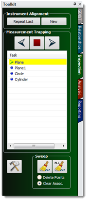
Often times, a specific instrument alignment process needs to be repeated to inspect a series of the same type of part or to repeat similar setups of an instrument at the same location. Under the Inspectiontab of the SA Toolkit, you will find Instrument Alignment options. From there, you can either create a New alignment or use the Repeat Last alignment command. Measure Nominal Points, Frame Wizard, and Quick Align to CAD can be repeated, making alignments easier to set up. Whenever an instrument is aligned, the alignment parameters are stored with the instrument in SA, so alignment can then be repeated at any time. SA will automatically recall the previously saved alignment parameters, which can be modified or committed at anytime.
USMN & Bundling
Click here to learn how to network a group of instruments using USMN or bundling.
Questions? Contact NRK at support@kinematics.com.
Sign up to receive our eNewsletter and other product updates by clicking here.