Measurement Simulation: Planning a Measurement Task to Save Time
 Often times, measurement tasks must be performed with minimal preparation. If you have the opportunity to prepare a job in advance; however, you may be able to minimize measurement time and simplify the measurement process. SpatialAnalyzer (SA) provides a number of powerful tools that allow you to run instruments in simulation mode and plan the placement of instrument stations at a job site in order to optimize the entire process. Read on to learn about SA’s planning and simulation options.
Measurement Simulation: Planning a Measurement Task to Save Time
Often times, measurement tasks must be performed with minimal preparation. If you have the opportunity to prepare a job in advance; however, you may be able to minimize measurement time and simplify the measurement process. SpatialAnalyzer (SA) provides a number of powerful tools that allow you to run instruments in simulation mode and plan the placement of instrument stations at a job site in order to optimize the entire process. Read on to learn about SA’s planning and simulation options.
Running an Instrument in Simulation
Most instrument interfaces can be run in simulation mode. This mode allows an operator to change tooling, adjust measurement profile settings, point at targets, simulate measurements, and more. It allows you to operate the basic menu functions just as you would when using a real instrument. Being able to perform measurement simulation can also be helpful for learning the basic operation of an instrument interface.
In order to simulate running a laser tracker, follow these steps:
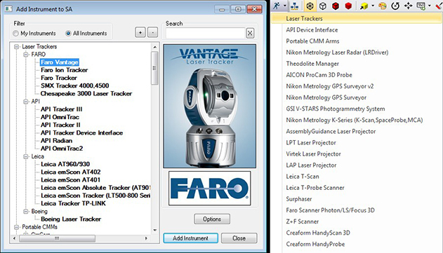
- Add the Instrument model to connect to (Instrument>Add…) and select the appropriate tracker from the available instruments.
- Run Interface Mode without connecting (Instrument>Run Interface Mode) and choose Laser Trackers (or API Device Interface for API tracker). You can also use the down arrow next to the running man icon as shown below.
- Select the tracker model you just added to your job file from the list of instruments in the Connect to SpatialAnalyzer dialog, then press OK. This will bring up a Faro Connection dialog box.
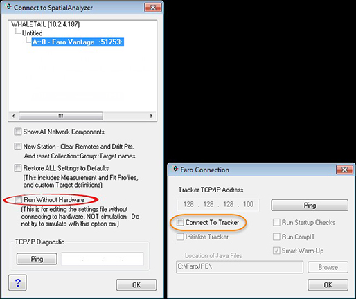
- Be sure to Uncheck the Connect to Tracker check box and press OK. This will connect the simulator to your instrument model in your job file.
The Run Without Hardware option in the Connect to SpatialAnalyzer dialog provides a different function than regular simulation. It allows a user to run the real instrument interface using the saved instrument settings persistence file. This does not allow you to simulate measurements, but it does provide the ability to define custom measurement profiles and define special tooling all prior to connecting (these are also available to you with the actual instrument once you reconnect). These tooling and measurement profiles can also be saved in a *.msp file that can be moved from computer to computer or saved as a backup for future use.
Simulating Other Instruments (PCMM Arms & Total Stations/Theodolites)
You can also run an arm in simulation mode following the same steps as those used for the tracker. Select Run Interface Module>PCMM Arms. Select the arm model to connect to and uncheck the Connect to Arm check box. To simulate using Total stations and Theodolites, you must first start the Theodolite Manager. The connection process for these instruments is as simple as not entering connection method or COM port.
Fabricating Measurements
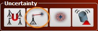
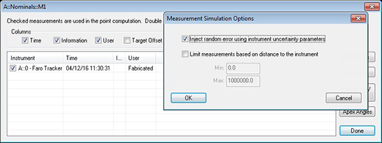
As an alternative to running your instrument in simulation, you can directly fabricate measurements from an instrument model or multiple instruments to a set of points all at once. This can be done with the command Analysis > Measurement Simulation > Fabricate measurements (or using the button in the SA Toolkit).
This will turn a constructed point into a “measured” point by adding a fabricated observation to that point and saving that within the points’ Measurement Details just as regular measurements are saved. It also offers the ability to limit measurements based upon a distance threshold and induce random error using the instrument’s uncertainty parameters. This is a useful tool for making simulation more realistic.
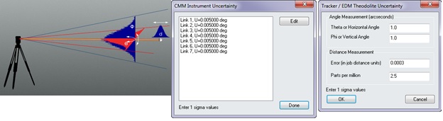
Instrument Uncertainty Estimation
No measurement is ever perfect because no instrument is perfectly accurate, particularly in a rough environment or at a great distance. The extent of the error only matters with regards to the tolerances you need to meet, so the ability to estimate measurement accuracy when planning a job can be helpful. In order to do this, SA provides a basic set of uncertainty controls for each instrument type that allow you to visualize the influence of error on a particular measurement at a particular location. To model this, SA saves uncertainty parameters as part of the instrument model properties in the tree.
When you fabricate a measurement in SA, the uncertainty values are automatically used to induce a small amount of error based upon the instrument’s uncertainty parameters. So, measuring the same point twice will not return exactly the same values, which is what you would expect during the actual measurement process.
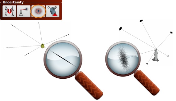
Furthermore, you can build an uncertainty cloud to visualize the extent of the expected error from that instrument with a given confidence. This is a quick way of replicating measuring a point, for example, 1,000 times. Doing so will produce a cloud of points, the shape of which will be the result of those uncertainty variables.
Take for example a comparison between a laser tracker and a total station. A tracker can measure distance quite accurately, while a total station tends to be more accurate with angles. The image below shows the significant difference in the shapes of the uncertainty clouds.
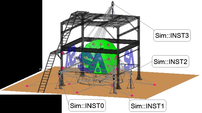
This uncertainty cloud computation process is the basis for more advanced network alignment operations. Unified Spatial Metrology Network (USMN) uses simulated measurements to determine the potential uncertainty of an entire network and plan the best placement of instruments within that network in order to reduce uncertainty. USMN is available in SA Ultimate only.
Detecting Obscured Points
Yet another useful function of simulation is the ability to tie together models of the facility with the instruments and measurements to determine line of sight restrictions and ascertain where measurements can and cannot be taken.
To help with this, SA provides the ability to detect measurements that are obscured within the job file. Use the function Construct>Points>Copy Point Group Excluding Obscured Points to build a list of shots that can be taken despite the restrictions and detect shots that cannot be taken based upon line of sight interference.
Greater detail on this topic can be found in a presentation made at a previous SA User Conference. The presentation can be accessed here:
http://www.kinematics.com/ftp/SA/Install/2015%20SA%20User%20Conf%20Presentations/Technical%20Presentations/
More detail about USMN can be found here:
http://www.kinematics.com/about/newsletterarticleinstrumentalignmentcontinued.php
Questions? Contact NRK Support at support@kinematics.com.
Sign up to receive our eNewsletter and other product updates by clicking here.