Relationships in SA - Part 1
 Metrology is the science of measurement, the art of defining the distance between objects in space. In order to make a measurement meaningful, you need a frame of reference or a coordinate system in which to base all of your measurements. A common challenge in metrology is converting from one coordinate system, such as that of a single instrument, to that of a larger more relevant frame of reference, like the coordinate system of an entire airplane.
 Relationships in SA - Part 1
Understanding the Value of Relationships in SA
Metrology is the science of measurement, the art of defining the distance between objects in 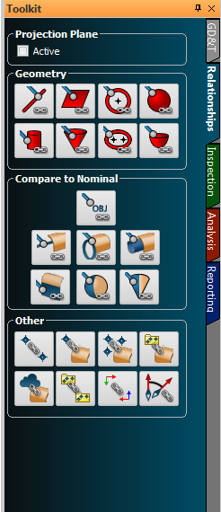 space. In order to make a measurement meaningful, you need a frame of reference or a coordinate system in which to base all of your measurements. A common challenge in metrology is converting from one coordinate system, such as that of a single instrument, to that of a larger more relevant frame of reference, like the coordinate system of an entire airplane.
Traceability is always maintained in SpatialAnalyzer® (SA), so measurements are always linked to the instrument that took them; however, the instrument may not be located relative to the larger coordinate system. SA allows users to align these coordinate systems through a variety of means, even after the measurements have been taken. One of the most dynamic and flexible ways to accomplish this is through the use of geometric relationships.
Like queries, relationships provide measurements of the distances between individual or groups of measured points and associated objects. Unlike queries, relationships update dynamically, providing a continually updating list of distances. If the object, such as a CAD model, is located in the global coordinate system, but the points are not, these relationships (or distance measurements) can be used to move the instrument so that the instrument’s coordinate frame is aligned with the larger coordinate system.
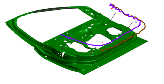
Imagine taking measurements of a control surface hinge for an airplane wing. You now have very accurate point measurements of that hinge, but those measurements are not aligned with the hinge model located in the airplane coordinate system. One way to align the measurements with the part is to measure the distance from each of your measured points to the nominal surface they represent. You can then move the instrument and measure again, making sure that each of the measured distances decreases. If you continually repeat this process, then you will eventually find a position in space where you can no longer move the instrument and reduce the overall distance of all your points from the object. Relationship optimization in SA can accomplish this automatically. The figure blow shows the Scan measurements being fit (aligned) to the CAD model of a car door panel.
Did you know that relationship fitting can be performed with any relationship in your job file and is available in both SA Professional and SA Ultimate? To use it, simply build a relationship between your part and your measurements and go to Relationships>>Move Objects by Minimizing Relationships. Below are a few additional tips that will help you
visualize your alignment and optimize the process:
- Relationships can be built before or after you make your measurements. Using the Relationships tab in the Toolkit bar, you can quickly build a relationship and then trap the measurements by double-clicking on the relationship in the Inspection tab. Alternatively, you can right-click on a relationship in the tree and select Associate Data, and then select the points or groups you want to use in the relationship.
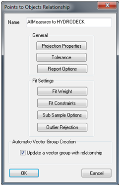
- If you have either a points or groups-to-objects relationship, you can right-click on the relationship in the tree, go to the relationships properties, and turn on an Automatic Vector Group. This vector group will update continuously as you move your instrument or take additional measurements, and it will give you a magnified visual indicator of the distance each measured point is from the part.
- Under the fit setting for the relationship, there is an option to turn on Outlier Rejection (see figure to the right), which automatically removes outliers from your data set. Once activated, points that are beyond a predefined high and low tolerance will be excluded from the fit solution so they don’t throw off your fit.
- If you find yourself working with a large data set (from a scan, for instance), SA provides a number of intelligent Sub Sampling Options (see figure to the right). Sub sampling can be performed using every i-th point or using a random distribution of points below a defined maximum number. This option can greatly increase the speed of a relationship fit without significantly reducing the accuracy of the final result.
With SA Ultimate, you have even more options at your disposal for relationship fitting. You can build multiple relationships and evaluate them all at the same time. SA provides a number of useful ways to determine which relationships have the most influence on the resulting fit.
- The influence of each relationship is determined by the Fit Weight. By default, each point in each relationship has the same influence on the fit (just as if you were fitting all the points to the model at the same time in a single relationship). If you want each relationship to have the same influence on the fit, regardless of the number of points in the relationship, use the Normalize Weighting button on the top of the Minimize Relationships Dialog. This gives you the ability to normalize based on the number of relationships, the combination of the number of relationships and their assigned tolerances, or simply by the number of measurements.
- Tolerances for each relationship can be added by right-clicking on the relationship. Surfaces with tighter tolerances are given more influence in the fit than those with looser tolerances, which can be used in the weight normalization process.
- Fit constraints are another way that relationship fitting can be defined in order to find an optimal solution. Fit constraints define a high or low region within which a relationship has no effect. It allows the fit solution to solve solely based on the other relationships as long as the fit is within the predefined bounds.
- Once the parameters for the fit are established, the optimization can be run by pressing the Run Optimization button (see figure to the right). SA makes small progressive movements of the instrument and associated points until the overall RMS is reduced as much as possible. The optimization can get stuck in a local minima in which no small movement of the data will reduce the overall RMS. Depending on the application, this may not be an issue, but running a Direct Search Optimization provides a tool to solve this problem.
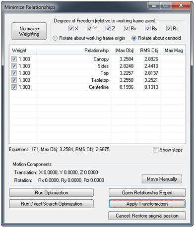
It is also useful to remember that the transform has not yet been applied until you hit the Apply Transformation button (see figure above), so you can zoom and rotate the graphical view and rerun the optimization as many times as necessary before accepting the final solution.
Aerospace Example of the Need for Multiple Relationships
 The trailing edge of an airplane wing is a good example of the need for simultaneous optimization of point-to-geometric shape relationships for spatial transformations. To efficiently manufacture optimal airplane wings, we need to optimize the position of the fittings that hold the trailing edge control surfaces relative to one another, and relative to the wing as a whole. Point measurements made of the control surface hinge line fittings have tight requirements normal to their design hinge line, while their position along the line is not as critical.
Measurements made on the spar’s web surface (the primary structure that holds the hinge fittings) have tight requirements normal to the design surface, but are not generally constrained on their position on the web surface. Measurements of the hole locations in the spar’s web that are used to rivet the hinge line fitting to the spar have known positions on the surface, while their distance normal to surface may not be critical. This is because the holes go all the way through the web structure; meaning the hole location on the surface is important, not the depth of the hole.
In this case, at least three points to geometry relationships should be created:
- First, the group of hinge line measurements should be constrained to their design hinge lines in the first relationship.
- A second relationship should capture the distance between the web surface measurements and the web’s design surface.
- The third relationship should hold the distance between the measurements of the holes to each hole’s design centerline.
Typically, control surface hinge line design requirements are tighter than web surface or rivet hole location tolerances. Therefore, the hinge line relationships should be considered more important and given a higher weight relative to the other relationships.
The best orientation of the measurements of the real part to the design geometry can be found by simultaneously optimizing the measured points against the constraints defined by the relationships. The optimization will yield the best spatial transformation between the measured point’s current position and the new position that minimizes the relationships and helps produce the best wing.
Click here to read Relationships in SA - Part 2
Questions? Do you have any hints or tips of your own that you’d like to share? Contact NRK at support@kinematics.com.
Sign up to receive our eNewsletter and other product updates by clicking here.