Scanning in SA
 It’s easy to quickly gather measurements on a part using a scanner. What you do with that mountain of data afterward is the source of most scanning-related headaches. Fortunately, SpatialAnalyzer offers a variety of tools to work with large scans and produce meaningful, accurate results. You don’t need a supercomputer or an engineering degree to get there. SA has evolved to support scanning applications, so read on to learn about several functions that will get you from cloud to report.
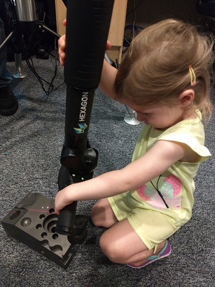
 Anyone Can Scan
It’s easy to quickly gather measurements on a part using a scanner. What you do next with that mountain of data afterwards is the source of most scanning-related headaches.
Fortunately, SpatialAnalyzer offers a variety of tools to work with large scans and produce meaningful, accurate results. The good news is, you don’t need a supercomputer or an engineering degree to get there. SA has evolved to support scanning applications, so read on for several functions that will get you from cloud to report.
Cloud Thinning (Intelligently)
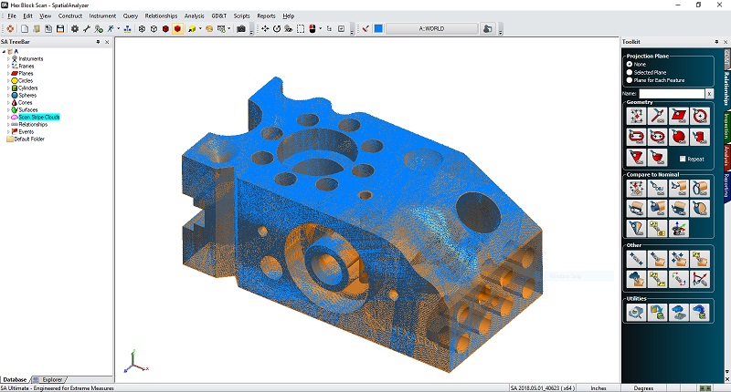
Modern laser scanners can quickly measure millions of data points. For most instruments, this data comes into SA as a point cloud. The original cloud is important to preserve for traceability’s sake, but there is often more noise than desired and a higher point density than practical.
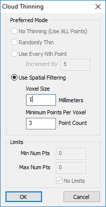
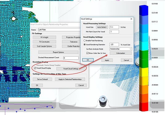
SpatialAnalyzer has a function available in many cloud operations to reduce the noise and density while maintaining traceability to the original measurements – this is called voxelization. The voxel approach allows the user to enter the desired voxel size, and the data is then essentially split into cubes of the desired size. Within each cube, only the best representative measured point is retained. By specifying a Minimum Points Per Voxel, fliers with no neighbors are easily eliminated.
Compare Clouds to CAD
Often you may just need to see the deviations of the measured part compared to how it was designed. The same tools that are used for probed points are available for clouds, i.e. query and relationship vector groups. You may make a Clouds to Objects relationship, turn off edge projections, and set a reasonable outlier rejection within the projection properties. Rather than making a very large vector group from this relationship (as you would with a relatively small set of probed points), it is often more appropriate to use Voxel Cloud Display. This thins intelligently and colorizes the cloud points. The same information is portrayed without the file size growth and graphical performance hit.
GD&T Inspection with Scan Data
With GD&T inspection, and especially when the tolerances of the part are approaching the capabilities of the instrument, oversampling may fail good parts. It’s very easy to oversample when you have a scanner. To mitigate the chance of random error and fliers influencing the inspection results, it’s a good idea to employ a voxelization strategy to the clouds used for GD&T analysis. This can be easily done when the clouds are associated to the checks via the Feature Inspection Auto-Filter.
For parts that have some large CAD faces (i.e. datum surfaces) and small features (i.e. true position of holes), it may be desirable to have several thinning settings. One can now run the Feature Inspection Auto-Filter Selected Checks once for each voxelization setting for the set of similarly sized features. It is also possible to have separate, additional thinning strategies for individual datums and feature checks.
Feature Extraction from Scan Data
If you’ve scanned a part to report features outside of the GD&T realm, you may just want to extract the geometry from the cloud. The workflow varies depending on what is available to you, but SA can find objects in the raw cloud with or without the help of nominal object information.
Extract Geometry from Cloud
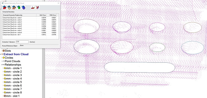
Even if you only have a cloud and no information in the form of a drawing or CAD model of the nominal part, SA can still extract features. Use the Extract Geometry From Cloud function.
![]()
Choose among plane, circle(s), slot(s), cylinder, and sphere; then pick a seed point graphically. SA will find the selected geometry in the proximity of the seed point and create a Geometry Relationship with the cloud points used in the solution. The fitted geometry can be annotated and reported the same as if it had been probed.
Auto Filter to Nominal
If you have the benefit of Nominal CAD, Nominal Geometry Relationships, or even a previously processed scan in which the extracted geometry can be used as a seed for extraction for similar parts, then Auto Filter of the cloud data is possible.
![]()
The two variations of the auto filter command, 2D or 3D, exist to properly handle whether interior feature data is available. For example, some circles can be constructed by projecting a cylinder fit to points on the interior wall of the hole to a plane fit to the surface near the hole. This process isn’t possible for small holes where the scanner cannot “see” inside, or thin parts (sheet metal) in which there is no data on the interior walls of the holes.
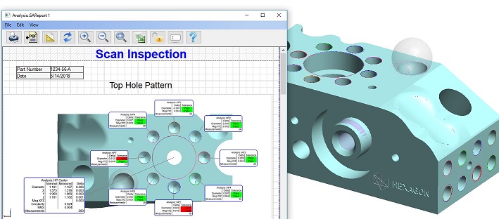
Regardless of the 2D or 3D filter strategy, the auto filter commands behave the same to the user. Given nominal geometry relationships (which can be created from CAD or SA objects), a measured cloud can be filtered by proximity to the nominal objects, and measured objects can be automatically created. Simply select the relationships and the measured clouds, then run the Auto Filter. With this approach, a report based on the nominal relationships can be prepared in a template, then going from scanning to reporting can be quick and simple.
For more information on scan processing strategies, or to see more details on these commands, check out the articles on the SA Community page or .Chapter 9 of the SA User Manual.
Questions? Contact NRK Support at support@kinematics.com.
Sign up to receive our eNewsletter and other product updates by clicking here.