Top 20 Tips for Using the SA Toolkit & Instrument Toolbars
 Continuing our celebration of NRK’s 20th anniversary, we give you our top 20 tips for using the SA Toolkit and instrument toolbars. The SA Toolkit provides intuitive, user-friendly tools that can streamline operations and provide easy access to some of SA’s advanced measurement capabilities.
 Top 20 Tips for Using the SA Toolkit & Instrument Toolbars
Continuing our celebration of NRK’s 20th anniversary, we give you our top 20 tips for using the SA Toolkit and instrument toolbars. The SA Toolkit provides intuitive, user-friendly tools that can streamline operations and provide easy access to some of SA’s advanced measurement capabilities.
Relationship Tab - Single Click Relationship Construction
-
1. Geometry relationships provide object oriented measurement with built-in traceability.
A geometry relationship provides dynamic control over geometry fitting. This means that every point you include in the relationship updates the geometry, and geometric properties can be modified on-the-fly. This makes your measured geometry completely dynamic while still maintaining the measurements’ history and instrument connections. -
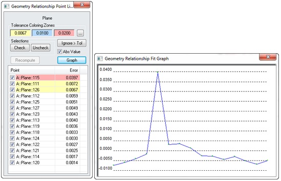
2. Points included in a geometry relationship can be viewed, updated, and sorted as needed.
The Geometry Relationship Point List shows the points you have included in the relationship, and allows you to set a tolerance or easily remove or ignore points that exceed that threshold. The “Graph” button enables you to visualize the point distribution.
-
3. The Geometry Relationship Fit graph can be left open for real-time evaluations as you take your measurements.
The properties dialog of a relationship must be closed in order to measure, but the graph can be left open. This allows you to view a real-time plot of the error included in a point set as you measure a feature. -
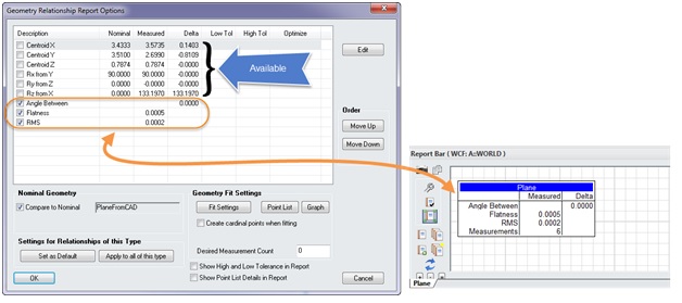
4. A nominal object can be added or changed at any point after adding a geometry relationship.
One of the best features of a geometry relationship is that it can provide immediate feedback on the deviation between a nominal feature and a measured feature. Many parameters are available for comparison, and the reported characteristics can be selected in the relationship properties dialog.
-
5. Geometry relationships can have cardinal points.
Cardinal points are points that define the centroid and normal direction of an object, such as the center point of a circle or the end point along the axis of a cylinder. Cardinal points in a relationship are dynamic and update with every measurement you take.
-
6. Don’t forget the “Apply to all of this type” button.
If you ever need to change the properties of multiple geometry relationships at once, you can use this feature. It will turn on/off cardinal points, allow you to change the fit settings, and set measurement counts for you.
-
7. Geometry relationships can be built from cardinal points, dynamically building geometry from
 geometry.
Dependent relationships can be set up in which changes are cascaded. As an example, suppose you wish to build a line from the center point of one circle to the center point of another circle. You can build this line before measuring either circle by adding the line to the circle cardinal points. Then, as you measure the circles, this line is generated automatically from the circle data.
-
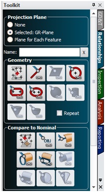
8. Any 2D geometry relationship can have a projection plane enabled. This projection plane can be added before, after, or during measurement and can be edited at any time.
With geometry relationships, you aren’t constrained by a strictly regimented measurement process. You can measure and construct geometry in the order that works best for you. -
9. Projection planes can be reused or redefined on a per-feature basis.
At the top of the Relationship Tab of the SA Toolkit are a set of radio buttons that define projection plane usage when features are built. A single plane can be defined for any number of features, or by checking “Plane for Each Feature,” a new projection plane will be added to the inspection tab and linked to each new feature you create. This allows you to iterate through each plane and each feature sequentially during the measurement process. -
10. The “Repeat” check box provides a means to add additional features automatically without returning to the computer.
When checked, this “Repeat” function makes it possible to build new features of the same type by using the “Iterate to next feature” button. This makes it possible to measure an unspecified number of circles or planes (for example) without specifying a measurement count in advance. New features are built with a single button click, all without returning to the keyboard. -
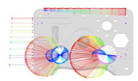
11. Auto-vectors can be built from any geometry relationship by adding a Points to Objects or Groups to Objects relationship.
By building a relationship between the measured points and the nominal geometry and turning on an auto-vector group, you can get immediate feedback on the alignment of your data to the part and quickly evaluate the deviation of particular features relative to their nominal location.
-
12. Dimensions are dynamic and update along with your geometry.
Any dimension you add to a geometry relationship or cardinal point will update automatically as the feature changes. This way you can rest assured that the reported distance is always correct even as updates continue to occur.
Inspection Tab – Scripting Through Advanced Object Creation or “Rinse and Repeat”
-
13. Measurement counts can be added for automatic advancement through an inspection.
Within the properties of each geometry relationship is a measurement count. When you start trapping to a feature, the number of points taken and the current measurement count is listed on the heads-up display. When you have measured the desired number of points for that feature, it will automatically move to the next feature in the list. -
14. Inspection “Rinse and Repeat” allows you to record as you measure and rerun the measurement process.
Relationships are independent of the points they use, so you can clear them at any time and associate new points. The Inspection tab provides quick access to this with a sweep function that will either clear a relationship or all the relationships at once. This way you can clear your measurements and easily run your inspection plan a second time. -
15. Repeat last alignment operation.
Measure Nominal Points, Quick Align to CAD, and Frame Wizard alignments can be repeated using the “Repeat Last” command in the SA Toolkit. -
16. Streamlined instrument toolbars are optimized for SA Toolkit workflow.
Tracker and arm measurement profiles have always been composed of an operation and acquisition, allowing you to specify the way in which you would like to measure and the resulting points or geometry you would like to return. The instrument toolbars are designed to take advantage of geometry relationships and are therefore much simpler. They allow you to easily set how you want to measure and start measuring. -
17. Single Point Circles.
With a projection plane already defined, a circle geometry relationship can be built by measuring a single point. The depth of the probe relative to this plane and the diameter of the probe allow you to build a circle with a single point. -
18. Loop and Iterate.
There is a “Loop and Iterate” option within the context menu for the laser tracker spatial scan measurement mode that allows you to build new features automatically every time you complete a loop. If you have multiple holes to measure, for example, you can simply use a stable start, set the reflector on a pin nest in the hole, and loop around the hole. Once the measurements are completed all the way around the hole, it will automatically go back into stable start, add a new feature, and be ready to measure the next hole without a single button click. -
19. Define new targets in the Tracker Toolbar by right-clicking on a target button in the toolbar.
By right-clicking on a reflector definition in the tracker toolbar, you can choose which target you would like the quick-select button to trigger. You can also choose to define a new target which will bring up the Reflectors and Targets Database and allow you to define custom tooling just like you would in the regular interface. -
20. SA Toolkit provides direct access to GD&T inspection.
GD&T checks can be built using CAD, SA objects, or even point measurements. The GD&T Tab is the one-stop location for building the annotations. Once built, the datums and feature checks will appear in the Inspection tab, which will guide you through the inspection process.
Questions? Do you have any hints or tips of your own that you’d like to share? Contact NRK at support@kinematics.com.
Sign up to receive our eNewsletter and other product updates by clicking here.