Auto Measure in SA
 Want simple tips that will help you save time with SA measurement processes? Below are a few easy shortcuts in SA that will help you accelerate measurement processes as well as simplify the process of locating measurements precisely.
Auto Measure in SA
Want simple tips that will help you save time with SA measurement processes? Below are a few easy shortcuts in SA that will help you accelerate measurement processes as well as simplify the process of locating measurements precisely.
-
Multi-Pass Auto Measure
While measuring the same features repeatedly at regular intervals over an extended time period can be useful for part evaluation, it can be a time consuming and tedious process. Luckily, SA has as built-in tool that allows known targets to be measured repeatedly at regular intervals without any user interaction. To start, set out know targets and measure them once in a single point group. Then go to Instrument> Automatic Measurement>Auto Measure and select the point group and the instrument you want to use.
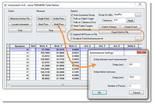
The keys to automation here are two fold. First, in addition to measuring the individual points in SA, a complete record of every observation can be recorded in a separate text file as you go (this file can be directly imported into Excel for additional analysis). Second, the Multi-Pass button allows you to repeat the measurement process at regular intervals. You can specify a delay time between individual shots and between entire passes for the points in the group to be measured. This makes it easy to automate the measurement process for any number of iterations. This method can be applied to any instrument that can be robotically pointed at a target such as a tracker or total station.
-
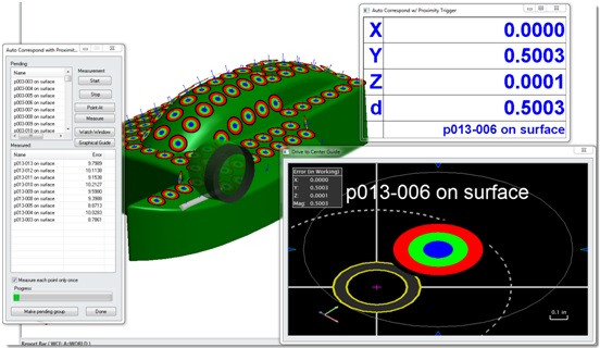
Auto-Correspond with Proximity Trigger
A great way to evaluate a curved part is to lay out a grid across the part and measure at each point on the grid. Doing this by hand with a watch window is time consuming, but you can make it easier by integrating a proximity triggered auto measure routine. To do so, build a grid of points on your part at the density you would like to use, then use Construct>Points>Layout>Grid by Distance overlaying your curved part.
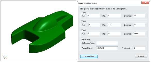
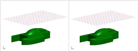
Next, project those points down onto the part using Construct>Points>Project Points to>Objects>Relative to Coordinate Axes>Parallel to WCF Axis. This will build a perfect XY grid of points projected onto the CAD model, which can be used to trigger measurements when a probe gets close.
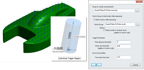
Occasionally, irregularities in a part can make it hard to get close enough to a nominal point to trigger a measurement. To avoid this problem, build a vector group from these grid points by going to Query>Points to Objects and overriding the probe offset to -1. This will create a uniform set of vectors at each point location with normalized vectors extending outward from it. You can then use the vectors to trigger your measurements rather than the points. This allows you to trigger measurements when you get within a proximity to the vector axis, eliminating any issues of getting close enough to the points you want to measure. The proximity trigger zone for vectors is defined as a cylindrical region with a length equal to the Point Distance Threshold and the width equal to the Vector Axis Threshold. Fine control of both the length and width of the trigger allows you to precisely trigger points, even in tight regions or slots between adjacent CAD surfaces.
Once the routine starts, you can simply run a probe over the part and it will automatically trigger measurements for specific locations every time you get within the trigger distance threshold. Ticking off points’ locations as you go keeps track of points that have been measured and those that still need to be taken. Once the majority of the points have been measured, you can bring up a Graphical Guide window that will help you navigate precisely to the remaining locations, finishing a precise grid measurement of a part.
-
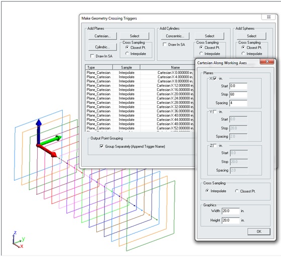
Utilizing Geometry Triggered Points Profiles.
Geometry Triggered Points available in both the tracker interface and arm interface provide not only a unique measurement tool, but also a sophisticated way to layout geometry in a symmetrical manner.
The idea behind Geometry Triggers is that the instrument is placed in a continual point scan measurement mode. The current position of the probe is monitored and points are only sent to SA when the probe crosses predefined trigger geometry. The simplest case is a series of planes laid out along an axis down a part. With these planes defined, you can scrub your part with the probe and get clean cross-section measurement divided evenly in separate point groups for each plane. This same concept can be applied to planes laid out radially or cylinders laid out in concentric rings.
The hidden advantage to this profile is that it provides an easy to way to build geometry in SA. If you ever need to lay out a series of planes or cylinders at regular intervals, there is no better way to build them than to use Geometry Triggers Profile to define the geometry within it. By clicking the Draw In SA button, this geometry is sent to SA and can be used for a variety of applications.
Questions about any of the shortcuts explained above? Do you have any hints or tips of your own that you’d like to share? Contact NRK at support@kinematics.com.
Sign up to receive our eNewsletter and other product updates by clicking here.