Commonly Overlooked Relationships in SA:
Frame Wizard Relationships & Pipe Relationships
 In SpatialAnalyzer (SA), Relationships are far more than a method for finding the distance between points and a nominal object that will re-compute automatically. In this article, we will review two types of Relationships—one new and one old that is often overlooked. Read on to learn more about Frame Wizard Relationships and Pipe Relationships.
 Commonly Overlooked Relationships in SA: Frame Wizard Relationships & Pipe Relationships
In SpatialAnalyzer (SA), Relationships are far more than a method for finding the distance between points and a nominal object that will re-compute automatically. In this article, we will review two types of Relationships— one new, and one old that is often overlooked.
Dynamically Updating Frames Using Frame Wizard Relationships
Have you ever needed to create an alignment using measured features? We all know the process: measure a set of features to define an alignment and then align to the nominal features. Did you know you can now delete points or re-measure others and the Frame (alignment) will update immediately? In addition, you can set up several different alignments in the same job for the same part and continuously monitor deviations in those alignments. Frame Wizard Relationships, added in the 2016.06.03 release, provides the ability to do just that.
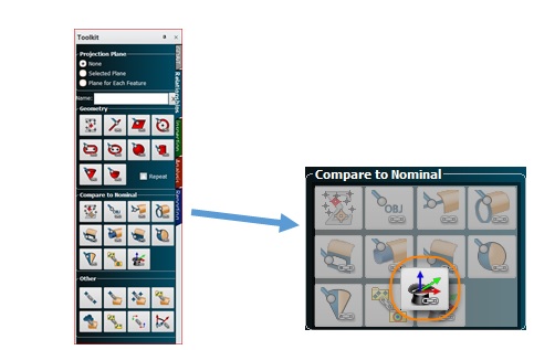
Frame Wizard has been a powerful tool in SA for quite some time. It allows the operator to quickly define an alignment (frame) from features measured in the job. Geometry Relationship Frame Wizard offers the benefit of re-computing the alignment instantly with the addition or subtraction of data. It also provides constant comparison between the measured and design frames providing dynamic feedback on your alignment. Give it a try next time you align. The function can be found on the Relationship tab of the SA Toolkit in the Compare to Nominal section. The SA Toolkit Side Bar can be found by right clicking in the blank space of the ribbon area and selecting SA Toolkit from the menu.
Pipe Alignment and Cut Optimization through Pipe Relationships
In industry, there is often a need to align mating sections of pipe. Measuring the location of the pipe sections is the first step, followed by calculating the cuts. In general, the goal is for these adjacent pipe sections to be as coaxial as possible and share enough material overlap so that a valid cut can be made. Pipe Relationship’s, available in SA Ultimate, will compute a cut plane for a single pipe as well as optimize joining multiple pipes. With SA’s Pipe Relationships, you can compute the cut angles and locations prior to any physical assembly; saving significant time and money during installation.
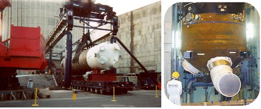
Consider this example of replacing a steam generator:
Since a power plant must be shut down to replace a steam generator—and because downtime at a power plant is very costly—anything that minimizes this is extremely beneficial. The replacement steam generator must be cut to fit prior to delivery. In this case, three massive pipe sections must be cut precisely. These piping interfaces are critical to the safety and performance of the power plant since they provide a direct barrier between the radioactive and non-radioactive sides of the plant; they must be aligned with precision.
Pipe Relationships in SA were designed with this type of high accuracy and complex alignment application in mind.
How to Use Pipe Relationships
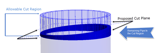
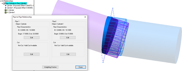
Pipe Relationships can be defined between any two objects that have positional and directional information. Typically, this refers to lines or cylinders. The type of object does not matter, as long as the object describes the pipe’s position and orientation. Once a pipe relationship is created, a proposed cut is displayed graphically. This is drawn in three pieces, a wire frame section representing the allowable cut region, a plane showing the proposed cut plane, and a solid rendered tube showing the remaining pipe section after the cut.
The allowable cut properties on each pipe can be edited in the relationship, including setting the inner and outer diameters of the pipe, and the position and length of each cut section (reported relative to the objects origin). These parameters are used for the cut plane computation. As soon as the pipe relationship can find a valid cut plane, it will display a dashed plane indicating the location and orientation of the cut plane, which will update dynamically based upon any changes in the properties of the cut or the physical positioning of the pipes in the job file.
When used in an alignment, Pipe Relationships work essentially as three relationships in one, the weighting of which can be controlled independently:
- It will try to make the pipe segments coaxial (Axis Offset).
- It will try to make the pipe ends parallel or at a predefined angle (Axis Alignment).
- It will try to overlap the cut regions evenly (Center Pull).
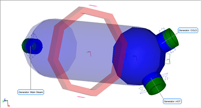
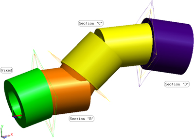
If there is more than one pipe segment that will be assembled (that is, if there will be more than one independently moving object in the optimization), then each moving object (pipe segment) should be placed into its own collection. This includes the objects defining the pipe endpoint, the pipe surface/cylinder, and anything else you want to rigidly move with that pipe segment. In this situation, you must use Relationships > Move Collections by Minimizing Relationships which will allow you to align segments as shown below.
Working with the Cut
Typically, the next step is to create a frame on the cut, which can then be laid off on the real pipe for cutting. To build this frame, simply select Make the Proposed Cut and then Create Frame on Cut from either Pipe Cut Properties dialog.
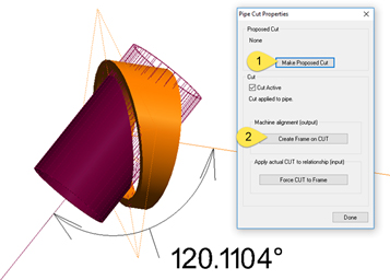
The frame defined will be the same for both pipes (although the direction is reversed) and the XY plane of this frame defines the cut plane. Watch windows can then be used to lay this cut off on the real pipe.
The reason that there are separate controls for both pipes is to allow you to follow a more exacting approach, which would involve laying off the cut on one segment, performing the cut on the actual pipe, then measuring the actual cut plane. The Force Cut to Frame button is provided to update the first cut to the actual condition so that the second cut can be updated in accordance.
By feeding this as-built cut location back into the pipe relationship, it can then be used to tweak the alignment once more. After the alignment is further tweaked, a new cut plane can be laid off on the other pipe segment. This process can be iterated as needed for each pair of pipe segments.
Relationships in SA continue to evolve in order to provide operators greater flexibility and control. They provide a way to combine the input points or features to build a dynamically computed feature that is automatically compared back to a nominal feature while ensuring perfect traceability. As such, Relationships provide the ideal user guidance tool and reporting solution.
Questions? Contact NRK Support at support@kinematics.com.
Sign up to receive our eNewsletter and other product updates by clicking here.