Fermi National Accelerator Lab: SpatialAnalyzer Means Greater Efficiency & Accuracy
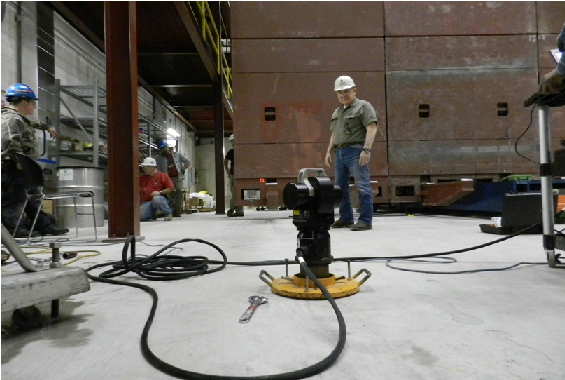
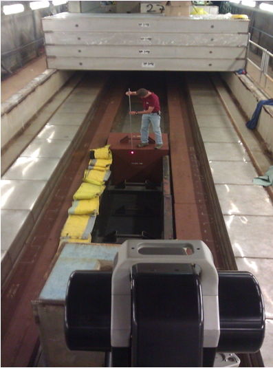
 Founded in 1967, Fermi National Accelerator Laboratory (FNAL, or Fermilab) in Batavia, IL specializes in high-energy particle physics research. Fermilab is the largest high-energy physics lab in the US with an accelerator complex comprised of ten particle accelerators and storage rings. To service the alignment needs of the accelerator complex, the metrologists at Fermilab have used SpatialAnalyzer ® (SA) with their laser tracker systems since 2000. Laser trackers provide the backbone for most of Fermilab’s metrology tasks, such as optical tooling, surveying, measurement, and aligning.
 Fermi National Accelerator Lab:
SpatialAnalyzer Means Greater Efficiency & Accuracy
Founded in 1967, Fermi National Accelerator Laboratory (FNAL, or Fermilab) in Batavia, IL specializes in high-energy particle physics research. Fermilab is the largest high-energy physics lab in the US with an accelerator complex comprised of ten particle accelerators and storage rings. To service the alignment needs of the accelerator complex, the metrologists at Fermilab have used SpatialAnalyzer ® (SA) with their laser tracker systems since 2000. Laser trackers provide the backbone for most of Fermilab’s metrology tasks, such as optical tooling, surveying, measurement, and aligning.

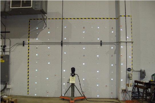
The Fermilab metrology team initially turned to SA because they needed a common software platform for gathering and analyzing measured position information in the field. From the start, they found that SA complemented the speed and accuracy of laser tracker systems very well. Today they use SA on a daily basis to support API laser trackers, a Leica AT401, three Leica Nivel 220, and to process data from a photogrammetric V-Stars system. The entire metrology group at Fermilab uses SA and finds it easy to use—even in the field. They say the rapid data acquisition is particularly helpful, while SA’s graphics capabilities provide a valuable visual aid when processing jobs.

Integrating Measurement Plans (MPs) has been a huge time-saver for Fermilab’s metrology  team because it allows them to streamline tasks that are performed repeatedly. In fact, they find the ability to create new, user-driven MPs on a regular basis to be the most valuable capability of SA. Implementing MPs reduces repeat tasks merely to a guided measurement process, saving Fermilab significant time and manpower.
MPs come in handy for an essential part of alignment tasks at Fermilab—referencing magnets. Referencing aspects are captured in SA in the form of MPs, which provides the information of the fiducial positions, mounted to the outer magnet body in relation to the geometric or magnetic magnet center line. Usually adjacent magnets need to be placed relative to each other on the order of +/- 0.125 mm or +/-0.006”. Therefore, in the error accumulation from the construction of the magnet to the final placement in a beam line, each step needs to be tightly controlled so that the sum of the individual RMS values does not exceed the stated position tolerance. To minimize the potential for errors during the referencing step, redundant measurements are used and MPs perform simple check calculations.
Sign up to receive our eNewsletter and other product updates by clicking here.