What's New in SA
SA Release 2011.08.05
Transparent Watch Windows
Watch windows can now be made transparent so that you can see the graphical view or other interface elements through the watch window.
![]()
To make a watch window transparent, right-click the window and select Transparent Background. To adjust the transparency of the watch window's frame, right-click the watch window and select Adjust Frame Transparency.
Multiple Graphical Views
SA now supports multiple graphical views for obtaining multiple perspectives on your job. Additional graphical views can be opened by selecting View > New Graphical View Window.
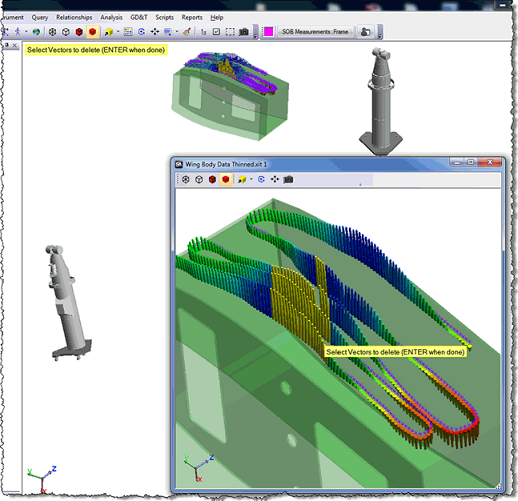
Auxiliary graphical views can be rotated, positioned, and rendered independent of the primary graphical view, and they also support selection. Hold the CTRL key while changing the render mode, autoscaling, or creating a snapshot of the screen to have the setting apply across all open graphical view windows.
Query > Group to > Multiple Groups > Organize by Groups
Use this new command to instantly compare several groups back to a reference group. This command will create multiple vector groups: One comparing the reference group to group A, another comparing the reference group to group B, and so on. This is useful for comparing drift checks or doing repeatability studies, enabling you to view deviations of multiple measured groups over time.
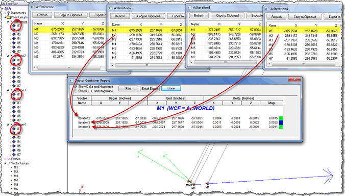
Query > Group to > Multiple Groups > Organize by Points
Similar to the "Organize by Groups" command described above, except the vector groups contain the same point as seen over time. This is particularly useful for viewing the variation of a specific point over time. See the following image to help illustrate this.
Geometry Fit Menus/Hotkeys
Menu items for Geometry Fitting (Construct > ... > Fit to Points) have been added back into the menus on user request These menu items automatically initiate Geometry Fit with the appropriate selected geometry type and put the interface into point selection mode for convenience. In addition, hotkeys have been added that support the most common Geometry Fit geometry types:
- Lines: Ctrl+Alt+L.
- Circles: CTRL+ALT+C.
- Planes: CTRL+ALT+P.
- Cylinders: CTRL+ALT+Y.
- Spheres: CTRL+ALT+S.
Geometry Fit Details
The Fit Details window in the Geometry Fit interface is now modeless, so you can leave it open while adjusting your fit parameters--the Fit Details will update dynamically. The window also remembers its state (open/closed) and position on-screen, and will reappear in the saved position upon the next use of the command.
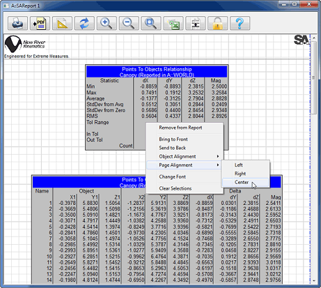
SA Report Alignment Tools
Dynamic Reports are now called SA Reports. Multi-select alignment commands have been added to align report elements to the page (left, center, right), align elements to each other (left/right/top/bottom/horizontal center/vertical center), and to align text (left/center/right).
Grids and Grid snapping have been added (these gridlines appear in the SA report but are not printed by default). Refer to the page settings (pictured below) for available options:
.png)
When multi-selecting report entities, they can be "nudged" with the arrow keys.
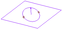
Construct > Points > Intersection > Plane and Circle
This new command will construct points at the intersection of a plane and circle. If the plane and circle do not intersect, no points will be created. If the plane is tangent to the circle, 1 point will be created.
Instrument > Locate > Frame Wizard
This command allows you to create a coordinate frame based on an instrument's measurements, and will simultaneously transform that resulting frame to the active coordinate frame. It is essentially a shortcut to combine the commands Construct > Frames > Frame Wizard and Instrument > Locate > Frame to Frame Transform.
Single-Object Relationship Fitting in SA Basic
For those users with SA Basic, rather than using Analysis > Best Fit Transformation > Points to Surfaces/Objects > N-Point Full Fit to Objects you can now perform a relationship minimization (Relationships > Move Objects by Minimizing Relationships) for a single relationship. This provides access to the reporting and degree-of-freedom capabilities of relationships.
Note: SA Basic users are limited to minimizing just one relationship. For simultaneous solutions of multiple relationships, SA Ultimate is required.
Construct > Frame > At WORLD Origin
This new command allows you to recreate a coordinate frame at the world origin in case the existing world frame was deleted or moved.
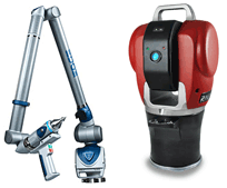
New Instrument Interfaces
Support for the new API Radian tracker and Faro EDGE arm has been added.
New MP Commands
- Utility Operations > Set Object(s) Translucency: Sets the rendering type and translucency for a list of objects.
- Construction Operations > Frames > Construct Frame - Copy And Make Left Handed: Creates a left-handed copy of a right-handed frame.
- Report Operations > Report Bar > Refresh Report Bar: Refreshes the Report Bar.
- Reporting Operations > Report Bar > Add Pictures to Report Bar: Adds specified pictures to the Report Bar.
- Reporting Operations > Capture Current View: Takes a snapshot of the current primary graphical view.
- Instrument Operations > Set Observation Status: Activates or deactivates an observation for a specified point.
- Instrument Operations > Get Number of Observations on Target: Obtains the number of observations of a specified point.
- Instrument Operations > Get Observation Info: Gets the information for the i-th observation under a specified point.
- View Control > Set Render Mode Type: Sets the render mode to wireframe, hidden edges remove, solid+edges, or solid shading mode.
Note: The View Control > Set Render Mode command is now deprecated. - View Control > Set Target Labels Use Full Names: Specifies whether target labels should be displayed using full Collection::Object::Target notation.
- Utility Operations > Directory Existence: Determines if a directory exists on disk.
- Construction Operations > Points and Groups > Construct Points on Surface(s) by clicking: Allows a user to create points on a surface by clicking the surface.
- Construction Operations > Surfaces > Construct Surface by Dissecting Surface(s): Dissects a surface into its constituent surface faces.
- Analysis Operations > Reverse Engineering > Send Points to Geomagic: Sends specified point groups to Geomagic (Power3 Bundle only).
- Analysis Operations > Reverse Engineering > Send Clouds to Geomagic: Sends specified point clouds to Geomagic (Power3 Bundle only).
MP Command Improvements
Generate Custom HTML Report: Now works properly with embedded files.
File Operations > File Import > Direct CAD Access: Now provides return values which provides an indication of non-fatal warnings during import, along with specific warning messages.
Other Improvements
Relationship watch window settings now persist for various relationship types.
Events can now be exported to an ASCII text file. (Right-click the event and choose Export).
Added the ability to create a default 6-DOF robot from the menu (Analysis > SA Machine - Robots and Machines > Add Machine > Add Serial Robot > Default 6-DOF Robot). Once created, you can then adjust the Denavit-Hartenberg parameters for each link to model any robot.
Tip: NRK has kinematic models for many industrial robots. Contact us with specifics and in many cases we can provide .manipkin files for you.
SA Machine kinematic entities (links) can now be added before or after a selected link. Right-click the link for this option. The SA Machine calibration interface now has a button to set the measured point coordinates in the tool frame. This is useful when calibrating using an SMR located somewhere on the tool, but not at the end effector center point.
The speed of tree manipulation for large files with many point groups has been increased significantly.
Objects with the Normals Point Inward flag (Spheres, Cylinders, Paraboloids, and Cones) will now render in the backface color when this flag is set.
The Hover dialog has been widened to better accommodate extremely long point and collection names.
A default hotkey has been added for running USMN: Alt+U.
A Make Nominals from Actuals menu option has been added to the Inspection context menu for GD&T. This allows you to specify the number of points to measure for an inspection by using existing measured points.
Direct CAD Access now supports additional file formats: Autodesk Inventor 2011 & 2012, JT 9.5, Solid Edge Synchronous Technology 3 (ST3), and CATIA v5 R20 (up to but not including Hotfix 63).
In the SA Software Development Kit (SDK), Collection Object Name Reference Lists now support object names with object type. For example, "MyCollection::MyPlane::Plane."
By request, the point on normal has been added back when creating cardinal points for circles, planes, and ellipses.
Automeasure Multi-pass now supports a Number of Passes setting.
For additional improvements, fixes, and changes, please see the SA Readme file, accessible through our download page.