What's New in SA
SA Release 2012.07.09
Click here to view this in pdf format.
SA Toolkit Bar
The SA Toolkit bar provides a set of new tabs for quick access to functionality related to GD&T, part inspection, analysis, and reporting.
New SA Features with the SA Toolkit:
- GD&T. What was formerly known as the GD&T bar has been brought on as a tab in the Toolkit bar.
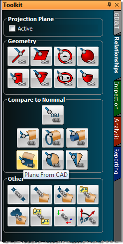
- Relationships. The relationships tab enables one-click definition of features (defined by CAD or using primitive geometry) primed for easy inspection using geometry relationships, with or without projection planes. Other relationships can be easily defined as well.
- Inspection. The inspection tab presents all trappable features from all collections—relationships, datums, and feature checks—in a single list. This allows you to easily advance through an inspection routine, trapping measurements for each feature, and instantly providing inspection results against nominal data.
- Analysis. Some of the more commonly-used analysis tools, such as the frame wizard and geometry fitting, are presented together in the analysis tab.
- Reporting. Functionality for creating reports, making dimensions, and creating/annotating callout views is gathered together in the reporting tab.
Reporting Enhancements
Headers/Footers & Templates
You can now define custom headers and footers for your own reports, including elements that update automatically (such as SA version,
page number, and date). Headers and footers can contain anything a report body can contain: images, text, tables, and fields—simply drag
elements as you would anywhere else on the report (see following image). While in the header/footer edit mode (accessible by doubleclicking a header/footer, right-clicking a header/footer or by selecting Edit>Modify Header/Footer from the report window), you can resize the
header/footer by dragging its divider.
When you’re happy with your header and footer, exit the mode by selecting Edit>Modify Header/Footer again. This will lock the header and footer in place, although dynamic fields will update as usual. If you’d like to set the report as a template for future reports, right-click the SA report in the tree and choose Default Template, or select File>Make Default Template from the report window. This can also be done through the User
Options>Reporting tab. Any additional reports created in the file will match the template’s format.
To use the template in other files, you can import the SA file containing the report template into the other file.
Keyboard Zooming
You can now zoom in and out in the report window using the + and - keys. Zooming to 100% can be accomplished by pressing Enter.
Jump to Page
Quickly jump to any page in your report by pressing Ctrl-G (for Go) while in the report window.
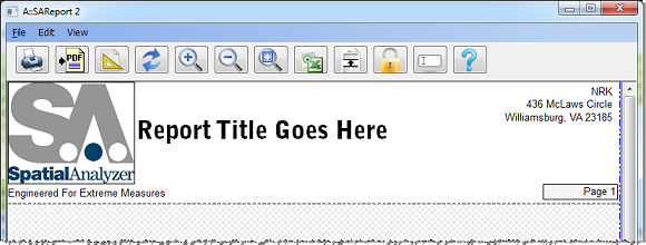
Image Border Control
Disable the display of borders around images from the report’s page settings options by clearing the Draw Images with Border checkbox.
Page Settings for Report Templates
Page settings for report templates can now be controlled from the SA Report Template properties dialog. In that dialog, click on the Page Settings button to define the parameters for the final generated report.
Assigned Reporting Frames
Individual objects can now be reported/displayed with respect to a specified coordinate frame—not necessarily the active frame. This allows you to have any coordinate frame active while always viewing a given object relative to its assigned coordinate frame.
To assign a specific reporting frame to an object, right-click the object and select Reporting Frame from the context menu.
Be aware that the reporting frame applies to reported values in the report bar and reports only. For example, when double-clicking a point to view its coordinates, you will always see the coordinates relative to the active coordinate frame, regardless of the point group’s assigned reporting frame.
Clipping Planes
Support for full clipping planes has been added to the graphical view. This is a great option when you want to 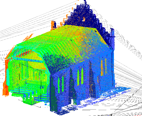 display a cutaway or crosssection of your data. You can define as many clipping planes as you’d like, and any of them can be active at any one time.
Any number of objects can define the position and orientation of clipping cubes, and each clipping cube can have up to six clipping planes. You can interactively drag and resize the clipping box to reposition the clipping planes.
For more information on View Clipping, see “View Clipping” on page 71 in the SA User Manual.
GD&T: Fit to Points
A new creation option has been added to GD&T: SA Objects (fit to points). This enables you to create a form or orientation GD&T check directly from measurements, instead of creating nominal geometry first.
For example, to perform a circularity check on a set of measured points, ensure that SA Objects (fit to points) is selected. Click the circularity button, select the measurements, then press Enter. The circularity results will be calculated immediately.
Tracker Interface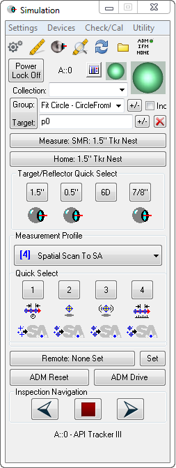
A number of enhancements have been made to the tracker interface in order to better communicate current target and measurement profile settings and provide access to common functions, as displayed at right.
- The Target/Reflector Quick Select box now displays text on the four pre-select buttons indicating the current target instead.
- An icon indicative of the current tooling setting is displayed underneath the quick-select buttons. These images indicate if the assigned setting is just for an SMR or is defined for use with additional tooling (such as a flat nest or pin nest).
- The four measurement profile quick select buttons now display icons underneath them indicating both the acquisition and operation modes for the profile assigned to each button.
- With all quick select buttons, you can hover over them to display the full name of the assigned tooling definition/measurement profile.
- For trackers that support a vision-based SMR locking mechanism (such as PowerLock or I-Vision™), a new toggle button has been added to the left of the interface docking icon to enable you to quickly activate or deactivate the locking functionality.
- A new Inspection Navigation box has been added to the bottom of the interface which enables easy navigation through trappable features. Easily advance forward or backward to the next trappable feature, or stop trapping altogether directly from the tracker interface.
Geometry Relationship Features
Several changes have been made to geometry relationships that improve flexibility and functionality.
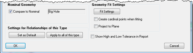
- Projection planes can now be defined for line, circle, and ellipse geometry relationships. This can be accomplished by either choosing the Project to Plane option in the relationship’s properties (above), or clicking the Projection Plane: Active checkbox in the Relationships tab of the SA Toolkit bar. In the latter case, the selected projection plane will remain active and apply to all following geometry relationships until the checkbox is cleared.
- Geometry Relationships can now be switched between “fit only” and “fit and compare” types. By selecting the Compare to Nominal option (above), you can select nominal geometry to use for “fit and compare” relationships. If you simply want a basic geometry fit relationship, simply clear the checkbox.
- Nominal Geometry can be created from the relationship properties. If you have an existing “fit only” relationship, you can create nominal geometry for it and convert it to a “fit and compare” relationship by clicking the Create Nominal button in the relationship’s properties.
- New menu item for fit and compare relationships. A new menu item (Relationships>Geometry Comparison>Select Nominal Geometries) has been added, along with a button on the SA Toolkit’s new Relationships toolbar, that creates fit and compare relationships from SA objects such as planes and circles. This is similar to Relationships>Geometry Comparison>Fit and Compare to Nominal, but doesn’t prompt for existing measured points.
- New option to clear point associations. Point associations for any type of relationship can now be cleared by selecting the new Clear Point Associations context menu item. This is available for both individual relationships and the parent relationship category in the tree. (From the SA Toolkit’s Relationships tab, you can also choose to delete the cleared points from the file).
- Access to fit settings prior to measurement. Geometry relationships now allow access to fit settings prior to assigning points, so you can now prepare the relationship in a template file prior to measurement.
Quick Align and Best-Fit Transformation with Cloud Points
Quick Align and classic best-fit transformation can now be performed directly with cloud points. This is intended to be used to align cloud data to CAD surfaces after measurement, and has been implemented to avoid the need to first convert clouds to points for use with the existing commands. Three new menu items have been added to support this: Analysis>Best-Fit Transformation>Point Clouds to Surfaces/Objects>Quick Align Clouds to CAD, Analysis>Best-Fit Transformation>Point Clouds to Surfaces/Objects>Point Clouds to Objects, and Instrument>Locate>Quick Align Clouds to CAD.
Frames from Probe Measurements
Frames can now be constructed from probe measurements (from devices such as the Intelliprobe 360 or T-Probe) if the measurements have probing direction information. Use the new command Construct>Frames>From Point Measurement Probing Frames.
Show Points
Selected points can now be shown in one command using the new View>Show Points command.
New MP Commands
For details on these new MP commands, see the MP Command Reference.
- Reporting Operations>Report Bar>Add Custom Tables to Report Bar. Adds one or more custom tables as tabs in the Report Bar.
- Reporting Operations>Custom Report Tables>Set Custom Table Cell Font. Sets the font for a specific cell in a custom table.
- Reporting Operations>Custom Report Tables>Delete Custom Table. Deletes a custom table from the tree.
- Reporting Operations>Set Scale for Picture. Assigns a scale value to a picture to control its size when added to a report.
- Reporting Operations>Append Items to SA Report. Sequentially adds one or more items to an SA report.
- Reporting Operations>Make New SA Report. Creates a new, empty SA report (using a defined template, if one exists).
- Reporting Operations>Output SA Report to PDF. Exports an SA report to a PDF file.
- Utility Operations>Copy Directory. Copies a directory from one location on the file system to another, optionally replacing the destination folder’s contents.
- Utility Operations>Set Notification Cancel Override. When enabled, the Cancel button and “X” in the corner of the window are not displayed in dialogs resulting from any “notification” command (such as Notify User String).
- Utility Operations>Set Automatic Backup State. Enables or disables full file and measurement automatic backups.
- Utility Operations>Move Robot/Machine through Path. Commands a robot/machine to pass through a sequential set of coordinate frames, optionally interpolating between those frames as linear segments or as a smooth spline.
- View Control>Set View Clipping Plane. Creates a clipping plane on a specified object.
- Construction Operations>Frames>Construct Frame - Average of Other Object Frames. Creates a frame with the average position and orientation of the supplied frames.
- Construction Operations>Other MP Types>Decompose Transform into Vectors (Origin and Axes). Converts a transform value into four vectors: one for the origin and one for each of the three axes defining the transform.
- Construction Operations>Other MP Types>Make a World Transform Operator (from Transform and Scale). Converts a separately supplied transform and scale factor in to a single world transform operator.
- Process Flow Operations>Ask for User Decision Extended. Provide a question or prompt and a series of choices to appear in buttons. Clicking a button will jump to a specified step. Similar to “Ask for User Decision”, except allows many more than three potential answers.
- Analysis Operations>Query Frame to Frame. Queries the delta between two coordinate frames.
- Analysis Operations>Query Point to Objects. Compares a point to one or more objects and returns the resulting deviation.
- Analysis Operations>Remove i-th Object From Collection Object Name Ref List. Removes the specified object from a collection object name reference list.
- Analysis Operations>Remove i-th Point Name From Point Name Ref List. Removes the specified point from a point name reference list.
- Analysis Operations>Auto Filter Points/Groups/Clouds to Surface Faces. Filters a set of points, groups, and/or clouds to a series of provided surfaces. Equivalent to the Construct>...>Auto Filter to Faces commands.
- Instrument Operations>Dock Instrument Interface. Docks or undocks an instrument interface to the SA user interface.
New MP Editor Features
- Recent Files. A list of recent files are now displayed in the MP Editor.
- Moving Blocks of Steps. An entire block of MP steps can now be moved up or down in the MP Editor. Select the steps you’d like to move, then click the up or down arrow to move the set of steps as a unit.
New Robot/Machine Features
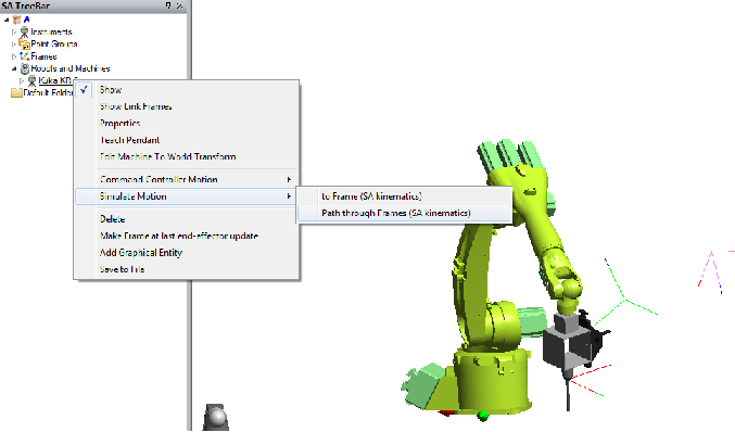
- Simulate Motion Through Frames. Right-click a robot or machine and select Simulate Motion>Path Through Frames to run the inverse kinematics calculation and display the robot’s pose at each of the selected frames.
- Command Motion Through Frames. Right-click a robot or machine and select Command Controller Motion>Run Path Through Frames to use manipulator kinematics to send frames directly to the controller, or have SA run a kinematics calculation and send joint sets to the controller for a calibrated path. Paths can be linearly interpolated between frames or via controller-created splines.
- Imported Joint Sets. For defining machine/robot poses, you can now import joint sets and match them with frames in SA instead of just importing points. To do this, right-click the calibration and select Import Joint Poses and Match to Frames.
Click here to view this in pdf format. For additional improvements, fixes, and changes, please see the SA Readme file, accessible through our download page.