SA Release 2019.05.16
 At New River Kinematics (NRK), we are dedicated to the continuous development of our core metrology software package, SpatialAnalyzer® (SA). We pay close attention to our users' feedback and regularly incorporate user suggestions into new releases. In fact, you'll find that we never stop improving and enhancing SA. Read below for the latest updates, enhancements, and fixes in SA Release 2019.05.16. Click here for the download page.
SA Release 2019.05.16
Click here to view this in pdf format.
Introduction of a Ribbon Menu
We have been listening. Customers have been asking for a simpler cleaner interface to SA for some time, and this release provides that. The ribbon menus integrate the toolkit with the standard menu functions controls in an organized and appealing menu structure.
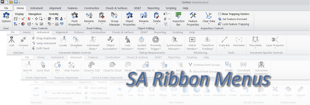
The ribbon menu is still under development with language translation and custom options still to come. So for the moment, it will need to be turned on using a check box on the Display tab of the User Options.
GR-Feature Inspection Enhancements
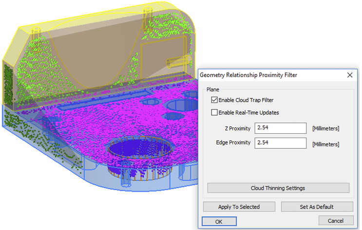
Feature specific cloud trapping capability
Compare to Nominal Geometry Relationships now offer the ability to be directly measured using scanning. A proximity threshold can be set on the nominal feature such that only data within the preset proximity is acquired while scanning. Settings have been added to allow filtering on the fly much like using multiple cloud clipping planes at one time. Surface face and edge proximity filters can also be asserted allowing feature specific cloud data to be collected.
Associate Proximity Cloud Points
A new right-click data association method was added to geometry relationships for proximity filtered cloud data. This option allows selection of a large cloud, and by selecting it, data is sub-sampled to acquire data within proximity to the nominal feature.
Added Filter Options for Lines
Added ability to filter points to lines within line geometry relationships (using proximity to the nominal line). We also added a single point line option as long as a nominal line is defined.
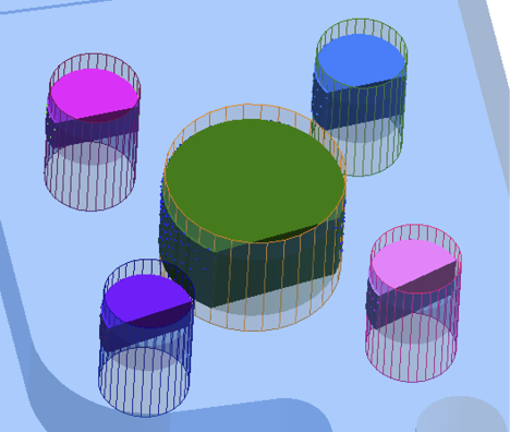
Improved Cylinder Visualization for Data Coverage
Several changes were made to cylinder construction to improve feature visualization while in Solid render mode. These include:
- Nominal Cylinders built from CAD are preset to be displayed in Wireframe mode.
- The point/cloud point coverage can now be displayed for a specific cylinder as part of the fit by showing a cylinder segment which expands as additional points are taken.
- A translucent cylinder shell is always displayed to clarify the actual placement of the cylinder full measured cylinder.
GD&T Enhancements
Direct Geometry Relationship Link
GD&T Annotations can now be directly linked to GR-Features. Doing so does two things: it ensures that the nominal feature from the geometry relationship is used in the annotation as the reference, and the feature check directly uses the points associated with that relationship. This eliminates the need to associate points with both the GR-feature and the feature check independently.
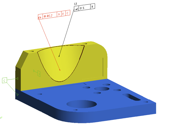
Surface Profile Auto-Detect Faces Option
Much like an All Over check, this option allows a single Profile check to be used to evaluate any surface with associated measurements. This option provides a helpful method in adding a “global” check for all measured surfaces.
Added Multi-Feature Datums
Datums based upon a group of features such as a bolt hole pattern can now be used as a single datum, limiting all but a single degree of freedom.
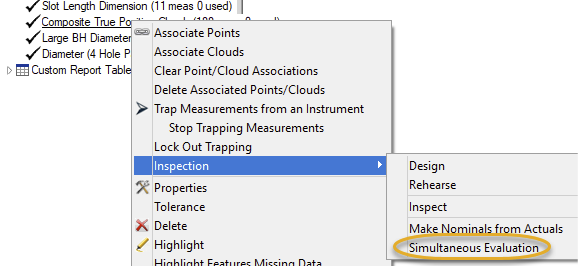
Simultaneous Evaluations
The ability to simultaneously evaluate all checks with a command datum reference frame (DRF) has been added. This can also be helpful in surface datum evaluations where a custom datum alignment is needed. Currently a single selected check can be used to initialize the alignment and all checks with the same DRF reference will then evaluate together.
Slot Length Added
Slot Length has been added as an additional dimensional option for GD&T evaluations. Both Width and Length can now be used as part of a material modifier for a position check on a slot.
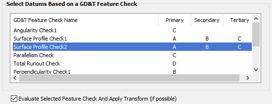
Check Specific Datum Alignments
Within the datum alignment tool you can now select a specific feature check, evaluate it and apply the final evaluated transform to your job file for troubleshooting and verification purposes.
Expanded Composite Check Reports
An additional separate set of Tables (both Datum and Tolerance Summary Tables and Point Details Summary) can now be built for Second Tier Evaluations in composite GD&T checks.
Added Per Unit Length Straightness checks
Straightness can now be evaluated in segments to allow gentle transitions over a given distance.
Show Only Active Feature Check
An option has been added to the Right-click menu of the feature check category that, when enabled, allows selective visualization of the selected feature check. This option hides all annotations not directly linked to the selected feature check, showing only annotations linked to the same faces and the referenced datums used by that check.
Callout Views Created on Import
A new collection: “CADViews: [file name]” is now added when you import a file with GD&T annotations. Callouts are included for each separate view included in the annotations and have layers set such that only those commonly oriented annotations are shown. This collection also includes a set of frames imported defining the annotation perspectives.
Point Cloud Enhancements
Point Cloud to Swatch Relationship
A new relationship has been added to both filter and evaluate point clouds relative to reference points on a part within a proximity zone.
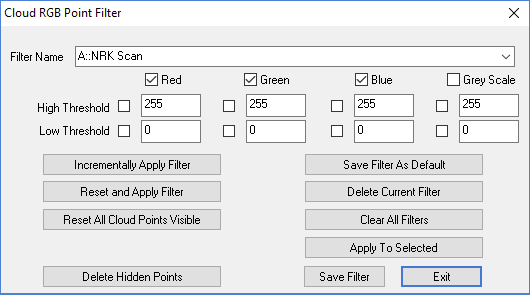
RGB Filtering
A new color based filter has been added to SA to allow both visualization and editing of clouds based upon saved color parameters such as Intensity and Incidence Angle.
Alignment Enhancement
Sequential Relationship Fit
The Sequential Relationship Fit option now includes the ability to group sets of relationships that can be optimized simultaneously as part of a sequential alignment process.
USMN Enhancements
Aperture Uncertainty Parameters Added.
Polar instruments such as Laser Trackers and Total Stations now have additional uncertainty parameters to better model uncertainty under all measurement conditions.
Reporting Enhancements
SA Report menus have improved graphics
Modified SA Report menu layout and implemented CTRL-wheel zooming. CTRL-middle mouse button will set zoom to 100%.
Added Alternate Time Display Formats
Added additional time display formats for report tags. This is performed under page settings and allows selection between the order of display in Time, Day, Month and Year as needed for regional reporting.
Instrument Developments
Nikon Laser Radar Update
Udated Nikon SDK from v8.2.2.3323 to v8.2.5.3840
Added Mitutoyo SpaceTrac series of Laser Trackers
Support has been added for these new tracker models through the use of the API Device interface.
New Leica ATS600
The ATS600 is the first reflectorless scanning tracker. The cloud data returned from the ATS includes intensity and quality information that can be displayed as a colorization of the returned point cloud.
Scripting
New MP Commands
- Construct Surface From Annotation Links. Command builds a new surface based upon the referenced CAD faces included in the input annotations.
- Make Annotation Ref List from a Collection. Creates a list of GD&T Annotations from a collection.
- Make Annotation Ref LIst- WIldCard Selection. Creates a list of GD&T Annotations using a wildcard selection method.
- Reverse B-Splines. Reverses the direction of the selected b-Splines
- Get Gradient AT Projected Point On Surface. This command projects a point onto the selected surface and returns the normal vector of the surfaces at the projected point.
- Get Gradient AT Projected Point ON Surface Edge. This command projects a point onto a surface, returning the normal vector, then the point is projected back to the reference B-Spline. The edge offset avoids ambiguous surface UV directions on a surface edge.
- Export ASCII Frames. Exports the selected frames in a pre-defined ascii format.
- Get Current Instrument Position Update. Returns the last position update from the selected instrument as well as a time from last update.
- Set Point Position in Working Coordinates. Allows a constructed points position to be directly modified.
- Transform Points by Delta (About Working Frame). Allows a selection of points to be moved a specified distance.
- Set Probe Offset Frame Online (Measure Raw Frame). Allows an offset frame to be programmatically assigned to a selected probe definition through measuring a frame.
- Set Probe Offset Frame Offline (Select Previously Measured Frame). Allows an offset frame to be programmatically assigned to a selected probe definition through selecting a previously measured frame in SA.
- Get Tracker/EDM Theodolite Uncertainties. Returns the uncertainty variables from the selected instrument model.
- Set Tracker/EDM Theodolite Uncertainties. Sets the uncertainty variables in the selected instrument model.
- Make Vector Group To Vector Group Relationship. This command builds a Vector Group to Vector Group relationship which can be used for gap analysis and sequential surface evaluation.
- Set Vector Group To Vector Group Cylindrical Zone. Defines the corresponding proximity zone used to correlate vectors in a VG to VG relationship.
- Set Vector Group To Vector Group Fit Weights. Sets the fit weights in a VG to VG relationship for gap alignment and optimization applications.
- Set Vector Group To Vector Group Fit Gradient Factor. Sets the VG to VG gap gradient factor used to define a progressive relationship constraint.
- Set Vector Group To Vector Group Relative Polarity. Used to determine the analysis method used by a VG to VG relationship.
CHAPTER
1