SA Release 2019.11.21
 At New River Kinematics (NRK), we are dedicated to the continuous development of our core metrology software package, SpatialAnalyzer® (SA). We pay close attention to our users' feedback and regularly incorporate user suggestions into new releases. In fact, you'll find that we never stop improving and enhancing SA. Read below for the latest updates, enhancements, and fixes in SA Release 2019.11.21. Click here for the download page.
SA Release 2019.11.21
Click here to view this in pdf format.
Ribbon Menu Improvements
Many language translation improvements.
User Interface
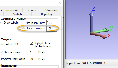
Added option to change coordinate indicator frame size
The size can now be specified in the users options.
Rename Improvements
Expand Rename Points by Proximity to rename all within the zone. Rather than renaming a single point, this function will now rename each point within the specified proximity to the target point and rename using a naming pattern (TB1, TB1-1, TB1-2, TB1-3, etc).
A new Relationship rename using a naming pattern was also added.
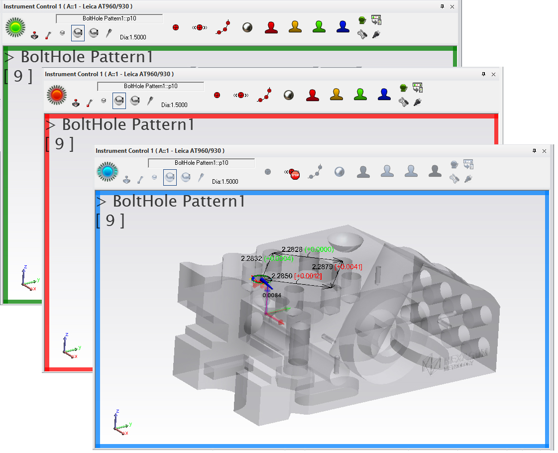
Heads Up Display Improvements
Add option in Heads Up Display HUD to change the background border color to reflect instrument beam state.
Improved Properties Control for Watch Windows
Watch windows have just become a lot easier to control and configure for a particular application through a new properties dialog.
Added means to persist Auto Measure settings
A new right-click option has been added to the Apply button within Auto measure that allows a user to save or persist the current settings.
Improved Delete Item Speeds.
Accelerated delete items by disabling relationship recomputation during the process.
Alignment Enhancement
Folder Move and Frame to Frame Option
Its now possible to combine multiple collections in a folder an move them manually or using a frame to frame transform. This will move all collections, instruments and points together an can help greatly in merging jobs together.
GR-Feature Inspection Enhancements
Scan Stripe probing direction is now used to define normal in plane fits
This ensures a planes normal direction is now always correct when working when fitting geometry to a cloud segment.
Simultaneous feature trapping
Its now possible to scan into multiple features at one time, capture only relevant data and when trapping stops, have the cloud points automatically filtered into their respective features.
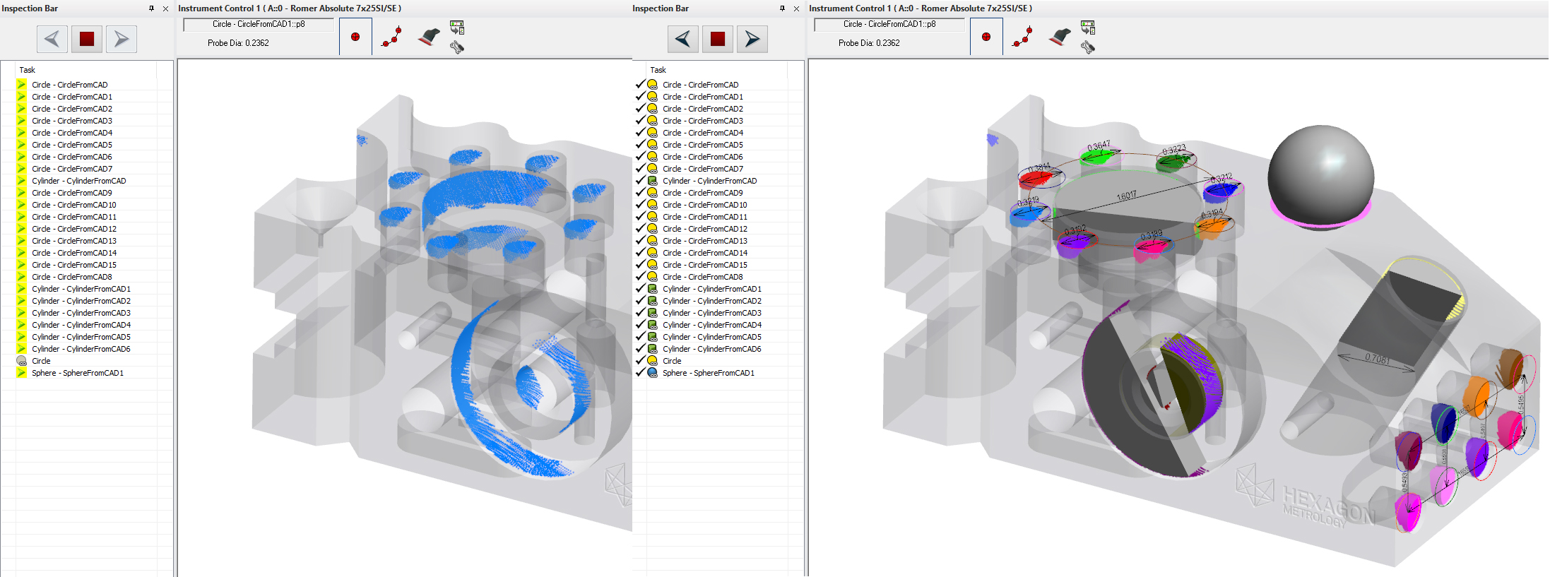
Improved Template Visibility
GR-Features are hidden until they become value with associated points. This concept has been carried through to dependant features such as intersection, features built from cardinal poitns and dimensions.
Expanded AVN vectors for Cylinders
There is now an option to display the AVN or nominal auto: vectors for cylinders as a set of cardinal point deviations at the nominal cylinder extents. This provides a means to evaluate alignment at the full length of the cylinder much more easily.
GD&T Inspection Enhancements
Show only Datums
Show only active Feature Check has been expanded to include selected datum features as well.
2D Slot Evaluate Option
An option has been added for slots to project Points to the Nominal Plane, allowing 2D slot evaluation for 3D slot measurements.
Per Unit Flatness Checks
Flatness checks can now be evaluated on a per unit basis in both width and length.
Cloud Point Enhancements
Cloud Display Control Enhancements
- Voxel Render Border. The depth and 3D nature of a voxel display is dependent upon a black border around the voxel. The thickness of this border can now be adjusted if the voxels overlap greatly and the color is overly black, or vice versa.
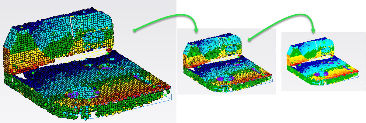
- Directional View Display. A right-click option has been added to a point cloud to allow its view only when aligned within 60 degree with the probing direction. This hides cloud points measured on the backside of a part making view of front side coverage much better.
- AutoZoom Cloud thinning. A fixed number of cloud points can now be displayed such that as you zoom in more points are displayed. This allows you to zoom in on a part and see all the individual measured points, while zooming remains fluid for viewing and rotation.
Added leading edge indicator in voxel and mesh display.
This new indicator makes it easier to see where the newly added scan lines are being acquired.
Added saved cloud point count control for plane in direct geometry extraction
Construction Tool Expansion
New Torus Construction Option for Fit to Points and cloud points
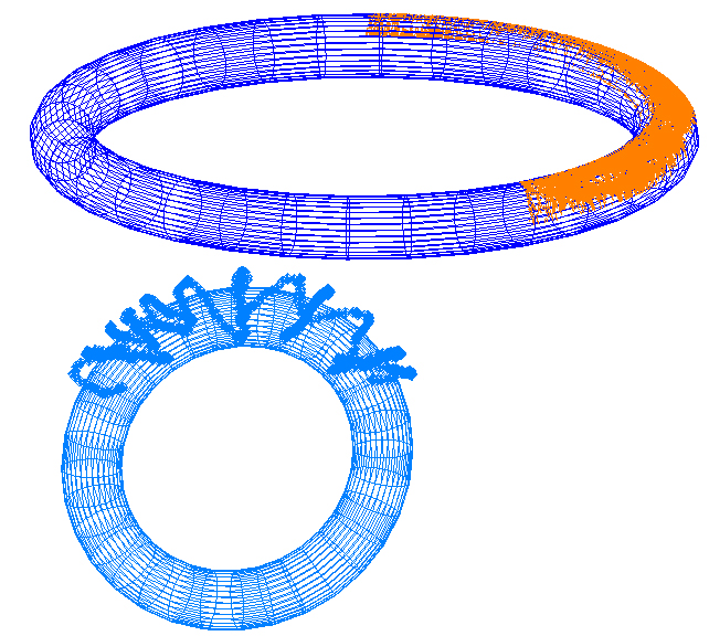
Torus construction is now an option through the geometry fit interface. This allows both construction of a fit torus to selected points or cloud points.
Add B-spline / Plane Intersection option
This option allows a use to select multiple planes and b-splines at one time and build the intersection points.
Construct Perimeter from CAD
- Perimeter from CAD Faces. This option allows you to build a bounding perimeter around any individually selected CAD face for precise region scan definitions.
- Bounding Perimeter. Using the selection of an instrument position along with the CAD a bounding perimeter can now be built in order to scan an entire surface.
Reporting Enhancements
Relationship Reporting Improvements
- Add Name Control to Points to Objects Column Title’s in Reports.
- Point to Point, Point to Object, and Frame to Frame reports have be updated and modernized.
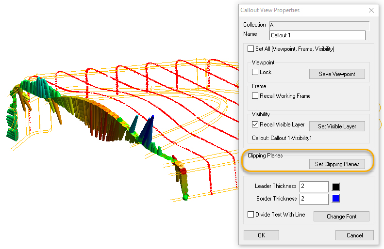
Callouts can now be linked to clipping planes
Much like recalling the working frame, a pre-defined clipping plane can be recalled and enabled when a callout view is enabled.
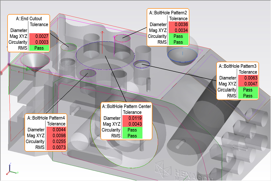
New Callout Arrangement Tool
A new optimization tool has been added to help arrange callouts in the graphic view such that they spread to the edge of the screen and remove overlap without any unwanted line crossing.
Add Min / Max Voxel Callout
When a relationship callout is added to a point cloud an additional voxel callout is automatically added to identify the max and min voxel.
Point to Object Component Dimensions
A set of simple radio buttons have been added to much more easily set a point to object dimension to display in 2D. A selection of XY, XZ and YZ controls have also been added.
Instrument Developments
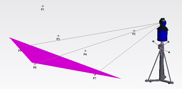
Added Show Obscured Shots display
We now have a quick and easy tool that can be used to check if points are visible from an instrument station. Right-click on the instrument and select Show Obscured Shots and choose a set of points to consider. This can be a big help in job planning applications.
Leica ATS600
- Add ability to use the existing Instrument>Automatic Measurement>Batch of Vectors tool to perform surface vector intersection measurements.
- Add Area Scan Cloud Profile to ATS Instrument Toolbar to replace the Red person
- Add new tooling Icons for the ATS measurement modes
CAD Import
Updated CAD libraries to support Autodesk Inventor 2020, Catia 2019, Creo 6.0 and more. See readme for details.
Scripting Enhancements
Added option in Rename points based on proximity... for rename multiple
- Get Obscured Points from Instrument. This command analyzes a set of points and returns a list of the obscured points along with an option to display shot lines to them.