SA Release 2022.1
 At SpatialAnalyzer, we are dedicated to the continuous development of our core metrology software package, SpatialAnalyzer® (SA). We pay close attention to our users' feedback and regularly incorporate user suggestions into new releases. In fact, you'll find that we never stop improving and enhancing SA. Read below for the latest updates, enhancements, and fixes in SA Release 2022.1. Click here for the download page.
SA Release 2022.1
Click here to view this in pdf format.
Interface Improvements
SA Ribbon Bar:
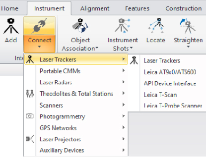
Instrument >> Interface >> Connect - Interface modules are now filtered by type to simplify and clarify instrument selection.
Inspection Improvements
Comparison Features
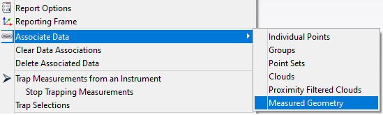
Geometry Relationships with a pre-defined nominal references now offer a new selection option: “Measured Geometry”. This geometry to geometry comparison still offers the ability to create cardinal points, vectors, and dynamic reports, and can be converted back to a full Fit and Compare relationship at any time.
Geometry Fit Expansion
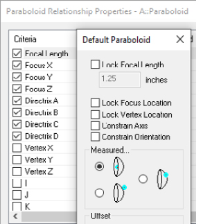
GR-Paraboloids now offer improved fit controls. This version adds the ability to constrain the fit process, fully holding the nominal axis or the nominal orientation during the fit process. These controls should be very helpful in antenna applications.
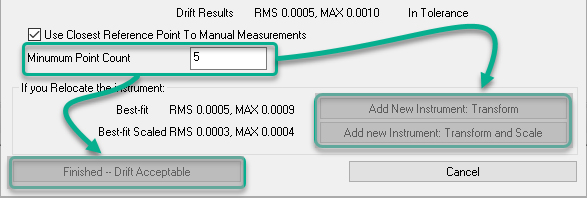
Minimum Point Count Added to Drift Check
At customer request there is now a minimum point count threshold that can be set within a Drift Check. When enabled, this control ensures the minimum number of points are measured in order to accept or realign based on the drift.
Drift Check: https://youtu.be/yeqdxTFztng
Cloud Based Inspection
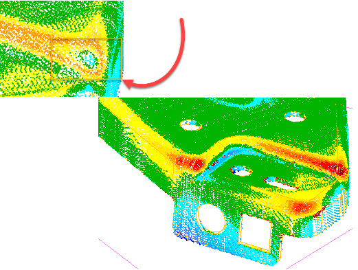
Probing Direction in CAD Comparisons
In prior versions of SA clouds were directly compared to the closest CAD surface. This could cause issues with thin sheet metal parts where the data is closer to the back side of the CAD.
In this version the probing directly has been incorporated in this comparison process ensuring that only the measured CAD surfaces are considered.
GD&T Inspection Updates
Organization and Access Improvements
In this version the ability to relocate existing annotations from one collection to another has been added.
Feature checks links are now associated with their corresponding annotations in the tree. This provides the ability to expand the annotation and directly access the feature checks built from this annotation.
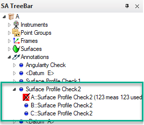
GD&T Annotations: https://youtu.be/62mO3GIYd7k
Import Improvements
New CAD Import Libraries:
- Autodesk Inventor 2022,
- Creo 8.0,
- FBX 7500
- NX 1980 series,
- Parasolid 33.1
Vector Import Improvements
The speed of importing vectors from a text file has been greatly increased.
Expand Point Set Use for Large Data Sets
Point Sets are more efficient than point groups for saving large data sets with thousands of points. In this version we have added:
- Ascii import options allowing the import of points as Point Sets
- Expanded our query capabilities to allow point sets to be handled as objects in a points to objects query or relationship. This facilitates closest point comparisons.
Reporting Improvements
Move Collections Logging
Extended logging to capture all variants of moving items through the Move option within the collection righ-click menu.
Fabricated Measurements
When measurements are associated with an instrument using the Fabricate Measurements option, the measurement details are now captured. The fabrication method parameters: inject error, limit distance, and min/max are all recorded.
Instrument Updates
Total Stations
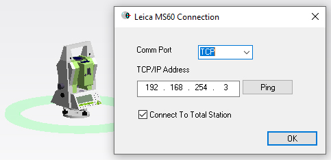
Added NEW! Leica Total Station Interface
A new interface has been added to improve support for Leica Total Station:
- Leica MultiStations such as the MS60
- Robotic Total Stations such as the TS16 and TS30
These instruments can now be run using the Leica Total Station interface as well as the Theodolite Manager. This new interface supports:
- Measurement profiles to measure single points, stable points, and spatial scans.
- For the MS60, the Nova Scan measurement profile supports Rectangle, Polygon and Dome scans in any configuration and can be saved with custom configurations.
- Turn ATR On / Off and Tracking On / Off using buttons on the Instrument dialog
- Clockwise and Swing checkbox in Power Search settings to allow left and right Power Search
- It also adds the ability to use SA Remote with Total Stations.
TS interface comparison: https://youtu.be/uDBnefiGRMM
Trackers
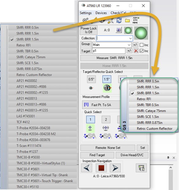
Improved Quick Select Display
A user noted that if too many 6D probes are present, the quick select list gets hard to manage and use. All current 6D targets that we automatically switch to upon beam lock will no longer appear in the list.
Expanded High Point Measurement Profile
High Point measure profile now supports 6D targets.
Leica LMF Trackers (AT960 and ATS600)
Added the ability to connect to trackers using serial number. The MP Command will now accept either serial number or IP in the IP address field.
Leica ATS600
Patch Scan gets a new parameter - Patch Angle. Patch Angle defaults to 45 degrees, to optimize measurement of Contrast Targets mounted vertically.
Leica AT960 with AS1 Scanner
Set Scan Profile []. Sets the RDS scan profile by name, designated by [] .
- “Start Scan”. Begins scanning.
- “Stop Scan”. Ends scanning.
Tracker MP Enhancements
Added MP Instrument Operational Check command to set any Spatial Scan profile increment parameter automatically.
This was added for use with the new control for simultaneous measurement where the tracker is controlled by an arm, but can be used any time.
PCMM Arm
Users can now manually calibrate an arm’s graphical model and save the solution into a file to ensure an accurate arm display. This is very helpful for arms that do not have a predefined encoder zero point.
On loading the SA job next time, the application verifies if the arm model has a pre-saved calibration file in the C:\Analyzer Data\Persistence directory. If found, the calibration offsets will be applied to the arm’s graphical model.
Faro USB
Updated Instrument.lst file to correct calibration parameters for FARO models to facilitate the graphic solution.
The Faro Quantum Max is now fully supported, including scanner transform retrieval from both scanner mounts. Faro Drivers v.6.9 or later are recommended.
Both 2meter and 3meter arm models were added to support the Quantum Max arm lineup.
To toggle between probing and scanning, you can now just hold down both arm buttons. Just press and hold both buttons until you hear the long press notification beep (about 2 seconds), then release.
PCMM Arm MP Enhancements
Added MP Instrument Operational Check command to set Arm Stream Points parameters. The command also ensures Stream is set to Spatial (not Temporal).
Laser Radar
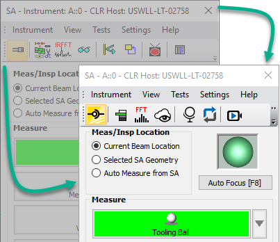
Nikon Metrology APDIS MV400 Laser Radar
Laser Radar APDIS MV400 has been integrated with Nikon CLR SDK v10.05.05.6082
The interface application appearance:
- Narrower interface layout
- Updated toolbar icons to improve visibility
- Improved target manager
Laser Projectors MP Enhancements
Aligned Vision (Assembly Guidance) Laser Guide
- Added MP commands “Set Auto Align File []” and “Auto Align”.
- Added MP command “Manual Align from Exported File []”. This allows you to prompt a manual (mouse drive) alignment for initial setup from a point group exported to an ASCII file.
MP Scripting Updates
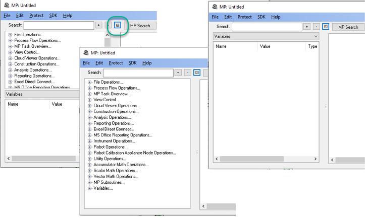
MP Editor Improvements:
Added a new expand/collapse button to the MP Editor that allows you to resize the Search and Connections/Find Results/Variables panel.
MP Script Updates
- Added the ability to reorganize the buttons within Ask for User Decision Extended.
- Added Limit Distance options to Fabricate Observations command.
- Added arguments to Drift Check to control a minimum point count.
New MP Commands
- Auto Arrange Callout View. Provides an automatic way to optimize the arrangement of callouts within a callout image.
- Get Feature Check Datum References. Returns a list of the datums used and object references for a given GD&T Check.
- Create Points to Objects Map. The command predefines a map of distances between points and objects that can be used to quickly detect objects within a proximity.
- Get Objects From Points to Objects Map (Point List). Returns a list of objects within proximity from a points to objects map.
- HTML Display Board. Initiates an HTML display that can be left active and updated while a script is running.
- Close HTML Display Board. Closes the open HTML Display Board.
Instrument List Variables
- Set a Collection Instrument Ref List Variable. Defines a variable containing a list of instruments.
- Get a Collection Instrument Ref List Variable. Returns a list of instruments from a variable.
- Get Collection Name and Index from Collection Instrument ID. Returns the name and index as separate entries.
Pipe Relationships:
Pipe Fitting Relationships can be used to define the ideal junction between two pipe segments. It allows you to compute a cut, measure the first cut end, recompute the second and build a perfect junction. This process can now be automated.
Pipe Relationships: https://youtu.be/Md7zXoFYeao
- Make Pipe Fitting Relationship. Builds a new pipe relationship between the selected objects.
- Set Pipe Relationship Weights. Defines the weighting parameters for the selected relationship.
- Set Pipe Relationship Segment Properties. Defines the pipe segments used, the amount of available material, the pipe cut process.
- Get Pipe Relationship Properties. Returns the relationship properties.
- Get Pipe Relationship Cut Status. Returns that current status of the cut process.
- Get Pipe Relationship Weights. Returns the weights currently set for the relationship
- Make Pipe Relationship Cut. Defines the cut status of one of the joining ends of a pipe.
- Pipe Relationship Force Cut to Frame. Resets the cut status from ideal to the measured cut location.
Robot Calibration Appliance
- Set Calibration Appliance Node Trapping Node ID.